


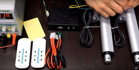
You have recently purchased an actuator and are excited to get your application up and running. However, after wiring all the devices together, the actuator does not extend or retract? Don’t worry, you’re not alone. With this guide, we will help identify possible causes of error and troubleshooting techniques that will help you get your actuator working as intended. Operating an actuator, for the most part, should be easy and straightforward, considering you already have all the right parts to get started:
- Actuator.
- 12 Volt DC Power Supply.
- Switches and/or Control Boxes.
- Brackets.
Here are some possible sources of error that you need to review or troubleshoot if your actuator doesn’t work.
Source of Power
There are typically two types of power sources that actuator users or installers typically use to provide 12VDC to the actuators motor – battery or power supply.
Power supplies are AC to DC converters that plug directly into a household outlet. These devices will convert 110/120VAC to 12VDC. Power supplies have various current ratings – this is important to note as the actuator that you are using requires a minimum amount of available current that must be provided by the power supply or battery.
Ensure that your power supply or battery can output the current requirement of your actuator. This information can be typically found on the label of the power source. For example, if your actuator has a current draw rating of 20A, the power source must be rated to output a minimum of 20A.
Wiring and Voltage Output
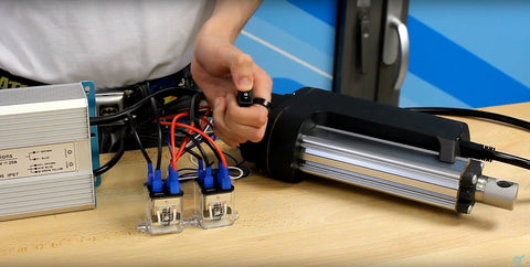
Multiple methods of control are available to extend or retract your actuator. Actuators are typically two-wire devices. This means that applying +12VDC to the actuator wires will extend the actuator shaft out. Reversing the polarity of the wires and applying -12VDC to the actuator wires will then retract the actuator shaft back in.
When no power is applied, the actuator’s shaft holds its position. This means that there must be a direct connection between the power source and the actuator wires to induce motion. If using a rocker switch, relays, or control boxes, ensure that the actuator is receiving +/- 12VDC. A voltmeter or a digital multimeter is recommended to measure voltage throughout your wiring.
- Check the power source (power supply or battery). Is your power source outputting 12VDC?
- Check the wires for continuity. Are all the wires intact and not broken?
- Check for loose connections. Have you tried disconnecting and reconnecting wires to attempt to resolve a possible loose connection?
- Check the output of the control box, switch, relay, or motor driver. Are you receiving a positive or negative 12VDC signal?
Still not receiving voltage to the actuator? We encourage you to review the wiring diagrams located on our website. These diagrams will assist with connecting your actuator compatible devices together
Still no movement?
If you are receiving a positive or negative 12VDC signal to the actuator and there is still no movement of the rod, the next step is to measure the current draw.
Using an ammeter, or by setting your digital multi-meter to the current measurement mode, take a reading of the current draw.
- Is the current reading zero amps? This means that there is no continuity in the circuit and the motor is not receiving power.
- Is the current reading the same value as the maximum current output of the power supply? This means that there is a short circuit and drawing a high current – If so, disconnect the power immediately as there is a risk of burning the motor and/or surrounding wires.
A current reading of zero may indicate an activated internal limit switch, possibly a defective or burnt motor, or a broken internal wire.
A short circuit may indicate water damage, melted wires, or burnt motor. A short circuit occurs when two wires that are connected to +12VDC and common on the power supply make a connection where otherwise unintended.
If there is no resolution
At Progressive Automations we have a team of highly skilled engineers who will be able to assist you with further troubleshooting steps and take corrective action if required. Please email us at sales@progressiveautomations.com or give us a call at 1-800-676-6123 for further assistance.