


Everyday, the machines and implements in our surroundings often make utilization of brushed and brushless DC motors to provide rotational motion. Both motors may look similar on the outside, however, their design and operation are quite different. It is important to select the right motor and ensure proper configuration for your application to have the best results. In this article, we will cover the difference between brushed and brushless motors to better understand which motor is most suitable based on their application. We will also show how to wire brushed and brushless motor connections to rocker switches for testing purposes.
Brushed DC Motor
A brushed DC motor consists of a few main components which in conjunction with a DC power supply create a rotating motor. The armature, commutator, brushes, and field magnet configuration can be seen in Figure 1 below.

Figure 1: Drawing (left) and actual example (right) of Brushed DC motors
Our drawing shows a simplified armature for an easier view of the current flowing through; however, brushed DC motors will have multiple coil windings with their armature. The brushes charge the commutator which delivers current through the armature in the opposite polarity of the permanent magnet. This causes the armature to rotate from the attraction of the magnets.
Brushed DC motors are easy to operate since they are among the simplest types of motors, however, they will have a shorter lifespan compared to brushless motors. Due to the brushes making physical contact with the commutator, sparking is a common issue with brushed motors. This physical contact also wears out the brushes over time and result in some energy loss from the friction generated.
Brushless DC Motor Controller
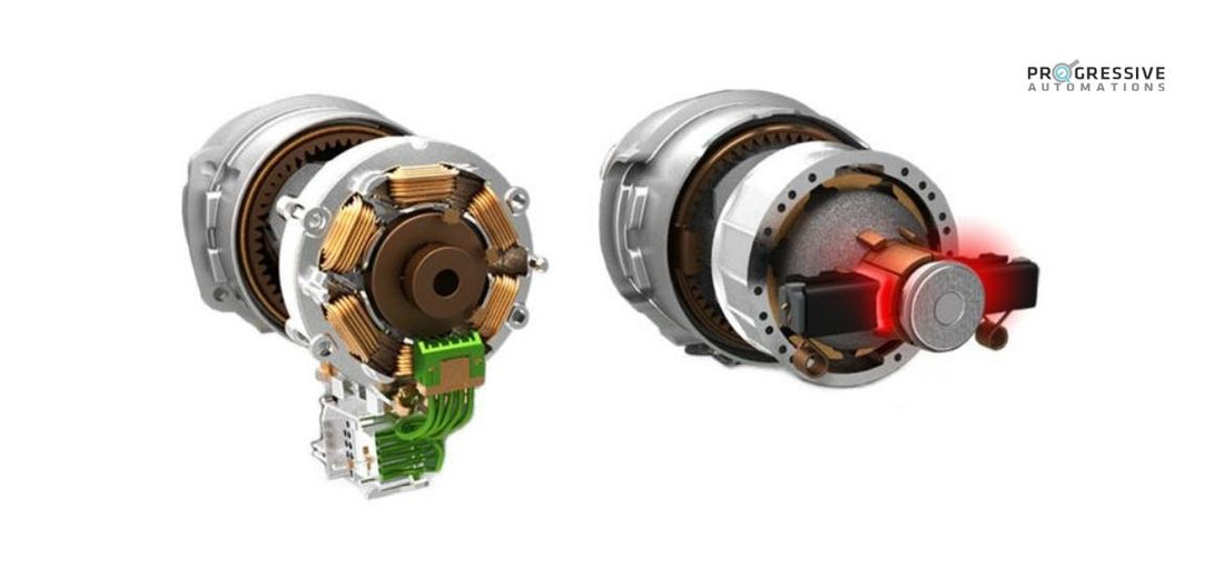
A brushless DC motor (BLDC) eliminates the major inefficiencies of its brushed counterpart. The motor is comprised of permanent magnets and coils, which through a series of perfectly timed energizing intervals cause the permanent magnet in the center to rotate around the coils that are surrounding it. We have included a brushless motor diagram for reference in Figure 2 below.

Figure 2: Drawing (left) and actual example (right) of Brushless DC motors
The coils in the brushless motor are energized in a specific sequence (Figure 3), which causes the permanent magnets on the rotor to rotate. This is done without any physical contact and allows for a more efficient, longer-lasting DC motor.

Figure 3: Coil energizing sequence
To follow the output shown in Figure 3, the brushless DC motor requires an Electronic Controller Unit (ECU), to determine the position of the rotor and which coils to energize.
Unlike the brushed DC motors which require 12VDC applied directly across the motor to rotate, the brushless DC motor requires 3 phase power. This means that a Brushless DC Motor controller must output the appropriate power to the different coils to achieve rotation. When using our LC-241 Brushless DC Motor Controller, 12VDC at 5A can be applied to the input terminals using a power supply. This is then converted to 3 phase power to control our brushless custom motors. In the next section, a basic wiring diagram will assist in testing a brushless DC actuator.
Wiring Brushless Motors to Rocker Switches
Progressive Automations currently offers the PA-14 Mini Linear Actuator in the Brushless DC option for custom orders. Our wiring schematic for Brushless PA-14 actuators can be seen in Figure 4 below.

Figure 4: Wiring schematic for Brushless PA-14 actuator
Step 1
Connect the 3 motor controller wires from the PA-14 Brushless Actuator to the LC-241 Brushless DC Motor Controller. The wires are typically green, blue, and white, which will connect to the U, V, and W terminals respectively. Ensure the brushless motor connections are tightly secured. If the wires are different colors, connecting them in the wrong order will simply move the electric linear actuator in the opposite direction than intended.
Step 2
Connect the SPD pin to the Ground of your 12 VDC power source to engage the built-in potentiometer for speed control. Make sure that this potentiometer is rotated clockwise for full speed.
Step 3
Connect the GND pin to the Common pins on your rocker switch.
Step 4
Connect the RUN pin to both sides of the rocker switch. This is important as both forward and reverse need the RUN pin making contact to Ground to function.
Step 5
Connect the REV pin to one side of the rocker switch. This side will be the reverse direction side of the rocker switch.
Step 6
Apply 12VDC to the brushless DC motor controller, an indicator noise can be heard on initial power-up.

Figure 5: Physical wiring of the brushless PA-14 actuator
The basic set up is now complete; using the rocker switch, the actuator can be extended and retracted. The issue with a brushless DC motor actuator is that the internal limit switches are not able to stop the power to the actuator like how it does for brushed DC motors. This is because the power going into the PA-14 Brushless Motor is 3 phase power. The PA-14 Brushless electric actuator comes with built-in limit switch feedback which can be utilized with a PLC or microcontroller to indicate that the actuator is at end of travel. The feedback acts as a Normally Closed to Normally Open switch which is essential to integrating a PA-14 brushless actuator into real-world applications.
We also have an article on Continuously Extend & Retract An Actuator Stroke With A Brushless DC Motor for reference with coding examples.
Wiring Brushed Motors to Rocker Switches
Most of our electric linear actuators come off the shelf with brushed DC motors. The easy operation of brushed DC motors allow for a rocker switches to be wired in between the DC power supply and brushed motor without any additional controller required.

Figure 6: Wiring schematic of a rocker switch to an actuator with brushed motor
The linear actuator wiring diagram above can be achieved by following a few steps:
- The upper-left and lower-right terminals must be connected to the ground of the power supply.
- The upper-right and lower-left terminals must be connected to the +12V terminal of the power supply.
- The middle-right and middle-left terminals must be connected to the 2 inputs from the actuator.
This type of actuator switch wiring allows their operator to change the direction of electrical current flow entering the actuator in order to change travel direction. For a physical example of an actuator wiring circuit with a rocker switch, this video is a great example.

Figure 7: Physical wiring of a rocker switch to an actuator with brushed motor
In Summary
Brushed DC motors have coils in their center rotating around permanent magnets while brushless DC motors have permanent magnet in the center that rotate around the coils. The brushless motor design is better suited for applications that will make use of its longer lifespan and greater energy efficiency. For a simpler and easier operation, applications with short cycle times can take advantage of the user-friendly design found in brushed DC motors.
If you have any queries or wish to discuss our products further, please do not hesitate in reaching out to us! We are experts in what we do and want to ensure you find the best solution for your application.
sales@progressiveautomations.com | 1-800-676-6123