Eri mallien iskunpituudet saatavilla pyynnöstä, lähetä sähköpostia osoitteeseen: sales@progressiveautomations.com
Tämä esimerkkikoodi käyttää MegaMoto Plussaa ja Arduino Uno -lautaa lineaarisen toimilaitteen virran seurantaan; vastaavat tuotteet voivat toimia korvaavina.
/* Koodi toimilaitteen virrankulutuksen (A) valvontaan ja virran katkaisuun,
jos se nousee tietyn raja-arvon yli.
Kirjoittanut Progressive Automations
19. elokuuta 2015
Laitteisto:
- RobotPower MegaMoto -ohjainkortit
- Arduino Uno
- 2 painiketta
*/
const int EnablePin = 8;
const int PWMPinA = 11;
const int PWMPinB = 3; // Megamoto-nastat
const int buttonLeft = 4;
const int buttonRight = 5;//painikkeet moottorin liikuttamiseen
const int CPin1 = A5; // moottorin palaute
int leftlatch = LOW;
int rightlatch = LOW;//moottorin lukot (koodilogiikkaa varten)
int hitLimits = 0;//start at 0
int hitLimitsmax = 10;//arvot, joista tiedetään, onko liikerajat saavutettu
long lastfeedbacktime = 0; // oltava long, muuten ylivuoto
int firstfeedbacktimedelay = 750; // ensimmäinen viive käynnistysvirtapiikin ohittamiseksi
int feedbacktimedelay = 50; // viive palautesykleissä; kuinka usein moottori tarkistetaan
long currentTimefeedback = 0; // oltava long, muuten ylivuoto
int debounceTime = 300; // painikkeiden poimintojen suodatus; pienempi arvo = herkempi
long lastButtonpress = 0; // ajastin poimintojen suodatukseen
long currentTimedebounce = 0;
int CRaw = 0; // syötearvo virtalukemille
int maxAmps = 0; // laukaisuraja
bool dontExtend = false;
bool firstRun = true;
bool fullyRetracted = false;//ohjelmalogiikka
void setup()
{
Serial.begin(9600);
pinMode(EnablePin, OUTPUT);
pinMode(PWMPinA, OUTPUT);
pinMode(PWMPinB, OUTPUT);//Aseta moottorin lähdöt
pinMode(buttonLeft, INPUT);
pinMode(buttonRight, INPUT);//painikkeet
digitalWrite(buttonLeft, HIGH);
digitalWrite(buttonRight, HIGH);//ota sisäiset vetovastukset käyttöön
pinMode(CPin1, INPUT);//aseta palautteen tulo
currentTimedebounce = millis();
currentTimefeedback = 0;//Aseta alkuarvot
maxAmps = 15;// ASETTAA MAKSIMIVIRRAN TÄHÄN
}//setup loppu
void loop()
{
latchButtons();//tarkista painikkeet, pitääkö liikuttaa
moveMotor();//tarkista lukot, liikuta moottoria sisään tai ulos
}//pääsilmukan loppu
void latchButtons()
{
if (digitalRead(buttonLeft)==LOW)//vasen = eteenpäin
{
currentTimedebounce = millis() - lastButtonpress;// aika viime painalluksesta
if (currentTimedebounce > debounceTime && dontExtend == false)//kun dontExtend on aktivoitu, ohita kaikki eteenpäin-painallukset
{
leftlatch = !leftlatch;// jos moottori liikkuu, pysäytä; jos pysähdyksissä, käynnistä
firstRun = true;// ohita käynnistysvirtapiikki
fullyRetracted = false; // kun liikut eteenpäin, et ole enää täysin sisäänvedetty
lastButtonpress = millis();//tallenna viime painalluksen aika
return;
}//if loppu
}//btnLEFT loppu
if (digitalRead(buttonRight)==LOW)//oikea = taaksepäin
{
currentTimedebounce = millis() - lastButtonpress;// aika viime painalluksesta
if (currentTimedebounce > debounceTime)
{
rightlatch = !rightlatch;// jos moottori liikkuu, pysäytä; jos pysähdyksissä, käynnistä
firstRun = true;// ohita käynnistysvirtapiikki
lastButtonpress = millis();//tallenna viime painalluksen aika
return; }//if loppu
}//btnRIGHT loppu
}//latchButtons loppu
void moveMotor()
{
if (leftlatch == HIGH) motorForward(255); //nopeus = 0-255
if (leftlatch == LOW) motorStop();
if (rightlatch == HIGH) motorBack(255); //nopeus = 0-255
if (rightlatch == LOW) motorStop();
}//moveMotor loppu
void motorForward(int speeed)
{
while (dontExtend == false && leftlatch == HIGH)
{
digitalWrite(EnablePin, HIGH);
analogWrite(PWMPinA, speeed);
analogWrite(PWMPinB, 0);//liikuta moottoria
if (firstRun == true) delay(firstfeedbacktimedelay); // pidempi viive, jotta käynnistysvirtapiikki ohitetaan
else delay(feedbacktimedelay); //pieni viive nopeuteen pääsemiseksi
getFeedback();
firstRun = false;
latchButtons();//tarkista painikkeet uudelleen
}//while loppu
}//motorForward loppu
void motorBack (int speeed)
{
while (rightlatch == HIGH)
{
digitalWrite(EnablePin, HIGH);
analogWrite(PWMPinA, 0);
analogWrite(PWMPinB, speeed);//liikuta moottoria
if (firstRun == true) delay(firstfeedbacktimedelay);// pidempi viive, jotta käynnistysvirtapiikki ohitetaan
else delay(feedbacktimedelay); //pieni viive nopeuteen pääsemiseksi
getFeedback();
firstRun = false;
latchButtons();//tarkista painikkeet uudelleen
}//while loppu
dontExtend = false;//salli moottorin pidentyä uudelleen sisäänvedon jälkeen
}//motorBack loppu
void motorStop()
{
analogWrite(PWMPinA, 0);
analogWrite(PWMPinB, 0);
digitalWrite(EnablePin, LOW);
firstRun = true;//kun moottori on pysähtynyt, ota firstRun uudelleen käyttöön käynnistysvirtapiikkien varalta
}//stopMotor loppu
void getFeedback()
{
CRaw = analogRead(CPin1); // Lue virta
if (CRaw == 0 && hitLimits < hitLimitsmax) hitLimits = hitLimits + 1;
else hitLimits = 0; // tarkista, onko moottori rajoissa ja onko virta loppunut
if (hitLimits == hitLimitsmax && rightlatch == HIGH)
{
rightlatch = LOW; // pysäytä moottori
fullyRetracted = true;
}//if loppu
else if (hitLimits == hitLimitsmax && leftlatch == HIGH)
{
leftlatch = LOW;//pysäytä moottori
hitLimits = 0;
}//if loppu
if (CRaw > maxAmps)
{
dontExtend = true;
leftlatch = LOW; //pysäytä, jos palaute ylittää maksimin
}//if loppu
lastfeedbacktime = millis();//tallenna edellinen palautteen vastaanottoaika
}//getFeedback loppu
Tämä esimerkkikoodi näyttää, kuinka ohjata jopa neljää lineaarista toimilaitettamme Arduino Unolla ja LC-82 MultiMoto Arduino Shield -kortilla; vastaavat tuotteet voivat toimia korvaavina. Koodi on tarkoitettu vain sellaisille toimilaitemalleille, jotka pysyvät MultiMoto-kortin kunkin kanavan virrarajoitusten puitteissa, kuten PA-14 ja PA-14P.
/* Esimerkkikoodi jopa 4 toimilaitteen ohjaamiseen Robot Power MultiMoto -ajurilla.
Laitteisto:
- Robot Power MultiMoto
- Arduino Uno
Kytkentä:
- Kytke toimilaitteet MultiMoto-kortin M1-, M2-, M3- ja M4-liitäntöihin.
- Kytke negatiivinen (musta) oikeaan liitäntään, positiivinen (punainen) vasempaan.
- Kytke 12 V virtalähde (vähintään 1 A per moottori kuormittamattomana, 8 A per moottori täysin kuormitettuna) BAT-liittimiin. Varmista, että napaisuus on oikein.
Koodia on muokattu Progressive Automationsilla Robot Powerin tarjoamasta esimerkkikoodista
<a href="http://www.robotpower.com/downloads/" rel="nofollow"> http://www.robotpower.com/downloads/</a>
Robot Power MultiMoto v1.0 -demo
Tämä ohjelmisto on julkaistu Public Domain -lisenssillä
*/
// sisällytä SPI-kirjasto:
#include <SPI.h>
// L9958:n slave select -nastat SPI:lle
#define SS_M4 14
#define SS_M3 13
#define SS_M2 12
#define SS_M1 11
// L9958 DIRection -nastat
#define DIR_M1 2
#define DIR_M2 3
#define DIR_M3 4
#define DIR_M4 7
// L9958 PWM -nastat
#define PWM_M1 9
#define PWM_M2 10 // Timer1
#define PWM_M3 5
#define PWM_M4 6 // Timer0
// L9958 Enable kaikille 4 moottorille
#define ENABLE_MOTORS 8
int pwm1, pwm2, pwm3, pwm4;
boolean dir1, dir2, dir3, dir4;
void setup() {
unsigned int configWord;
// kirjoita alustuskoodi tänne; ajetaan kerran:
pinMode(SS_M1, OUTPUT); digitalWrite(SS_M1, LOW); // HIGH = ei valittuna
pinMode(SS_M2, OUTPUT); digitalWrite(SS_M2, LOW);
pinMode(SS_M3, OUTPUT); digitalWrite(SS_M3, LOW);
pinMode(SS_M4, OUTPUT); digitalWrite(SS_M4, LOW);
// L9958 DIRection -nastat
pinMode(DIR_M1, OUTPUT);
pinMode(DIR_M2, OUTPUT);
pinMode(DIR_M3, OUTPUT);
pinMode(DIR_M4, OUTPUT);
// L9958 PWM -nastat
pinMode(PWM_M1, OUTPUT); digitalWrite(PWM_M1, LOW);
pinMode(PWM_M2, OUTPUT); digitalWrite(PWM_M2, LOW); // Timer1
pinMode(PWM_M3, OUTPUT); digitalWrite(PWM_M3, LOW);
pinMode(PWM_M4, OUTPUT); digitalWrite(PWM_M4, LOW); // Timer0
// L9958 Enable kaikille 4 moottorille
pinMode(ENABLE_MOTORS, OUTPUT);
digitalWrite(ENABLE_MOTORS, HIGH); // HIGH = pois käytöstä
/ /******* L9958-piirien käyttöönotto *********
' L9958:n konfigurointirekisteri
' Bitti
'0 - RES
'1 - DR - reset
'2 - CL_1 - current limit
'3 - CL_2 - curr_limit
'4 - RES
'5 - RES
'6 - RES
'7 - RES
'8 - VSR - jännitteen nousunopeus (1 = rajaus käytössä, 0 = pois käytöstä)
'9 - ISR - virran nousunopeus (1 = rajaus käytössä, 0 = pois käytöstä)
'10 - ISR_DIS - virran nousun rajoituksen poisto
'11 - OL_ON - open load -tunnistus päälle
'12 - RES
'13 - RES
'14 - 0 - aina nolla
'15 - 0 - aina nolla
*/ // aseta maksimi virtarajoitus ja poista ISR-nousun rajoitus käytöstä
configWord = 0b0000010000001100;
SPI.begin();
SPI.setBitOrder(LSBFIRST);
SPI.setDataMode(SPI_MODE1); // kellon polariteetti = matala, vaihe = korkea
// Moottori 1
digitalWrite(SS_M1, LOW);
SPI.transfer(lowByte(configWord));
SPI.transfer(highByte(configWord));
digitalWrite(SS_M1, HIGH);
// Moottori 2
digitalWrite(SS_M2, LOW);
SPI.transfer(lowByte(configWord));
SPI.transfer(highByte(configWord));
digitalWrite(SS_M2, HIGH);
// Moottori 3
digitalWrite(SS_M3, LOW);
SPI.transfer(lowByte(configWord));
SPI.transfer(highByte(configWord));
digitalWrite(SS_M3, HIGH);
// Moottori 4
digitalWrite(SS_M4, LOW);
SPI.transfer(lowByte(configWord));
SPI.transfer(highByte(configWord));
digitalWrite(SS_M4, HIGH);
//Aseta alkuasetukset: vedä sisään nopeudella 0 turvallisuuden vuoksi
dir1 = 0; dir2 = 0; dir3 = 0; dir4 = 0; // Suunta
pwm1 = 0; pwm2 = 0; pwm3 = 0; pwm4 = 0; // Nopeus (0-255)
digitalWrite(ENABLE_MOTORS, LOW);// LOW = käytössä
} // setup-loppu
void loop() {
dir1 = 1;
pwm1 = 255; //aseta suunta ja nopeus
digitalWrite(DIR_M1, dir1);
analogWrite(PWM_M1, pwm1); // kirjoita nastoille
dir2 = 0;
pwm2 = 128;
digitalWrite(DIR_M2, dir2);
analogWrite(PWM_M2, pwm2);
dir3 = 1;
pwm3 = 255;
digitalWrite(DIR_M3, dir3);
analogWrite(PWM_M3, pwm3);
dir4 = 0;
pwm4 = 128;
digitalWrite(DIR_M4, dir4);
analogWrite(PWM_M4, pwm4);
delay(5000); // odota, kun kaikki neljä moottoria on asetettu
dir1 = 0;
pwm1 = 128;
digitalWrite(DIR_M1, dir1);
analogWrite(PWM_M1, pwm1);
dir2 = 1;
pwm2 = 255;
digitalWrite(DIR_M2, dir2);
analogWrite(PWM_M2, pwm2);
dir3 = 0;
pwm3 = 128;
digitalWrite(DIR_M3, dir3);
analogWrite(PWM_M3, pwm3);
dir4 = 1;
pwm4 = 255;
digitalWrite(DIR_M4, dir4);
analogWrite(PWM_M4, pwm4);
delay(5000);
}//void loop loppu
Tämä esimerkkikoodi yhdistää Wasp-yksikanavaisen nopeussäätimen Arduino Unoon lineaarisen toimilaitteen ohjaamiseksi; vastaavat tuotteet voivat toimia korvaavina.
/*Esimerkkikoodi Robot Power Waspille.
Tämä ESC ohjataan RC-signaaleilla, joiden pulssit
vaihtelevat välillä 1000–2000 mikrosekuntia.
Ohjelman pääsilmukka pitää toimilaitteen paikallaan 1 sekunnin, pidentää 2 sekuntia,
pysäyttää 1 sekunniksi, vetää sisään 2 sekuntia ja toistaa tämän.
Muokannut Progressive Automations alkuperäisestä "Sweep"-esimerkkikoodista
Arduino-esimerkkikirjastoista.
Laitteisto:
- 1 Wasp-ohjain
- Arduino Uno
Kytkentä:
Ohjauspuoli:
- Kytke punainen/musta +5 V:iin ja GND:hen
- Kytke keltainen johto Arduinon signaalinastaan (tässä esimerkissä nasta 9)
Tehopuoli:
- Kytke moottorin virtalähteen +/- Waspin +/- -liitäntöihin
- Kytke toimilaitteen +/- kahteen jäljellä olevaan liitäntään
Tämä esimerkkikoodi on public domain -lisensoitu.
*/
#include <servo.h>
Servo myservo; // luo servo-olion servon ohjaamiseen
// useimmilla alustoilla voidaan luoda kaksitoista servo-oliota
int pos = 0; // muuttuja servon asentoa varten
void setup()
{
myservo.attach(9); // liittää servon nastaan 9
}
void loop()
{
myservo.writeMicroseconds(1500); // pysäytyssignaali
delay(1000); //1 sekunti
myservo.writeMicroseconds(2000); // täysi nopeus eteenpäin -signaali
delay(2000); //2 sekuntia
myservo.writeMicroseconds(1500); // pysäytyssignaali
delay(1000); // 1 sekunti
myservo.writeMicroseconds(1000); // täysi nopeus taaksepäin -signaali
delay(2000); //2 sekuntia
}
Tämä esimerkkikoodi käyttää releistämme ja Arduino Uno -lautaa lineaarisen toimilaitteen ohjaamiseen; vastaavat tuotteet voivat toimia korvaavina. Voit lukea lisää yksityiskohtia täydellisestä blogikirjoituksestamme.
const int forwards = 7;
const int backwards = 6;//määritä releen INx-nasta Arduinon nastaan
void setup() {
pinMode(forwards, OUTPUT);//aseta rele lähdöksi
pinMode(backwards, OUTPUT);//aseta rele lähdöksi
}
void loop() {
digitalWrite(forwards, LOW);
digitalWrite(backwards, HIGH);//Aktivoi rele yhteen suuntaan; arvojen on oltava erilaiset, jotta moottori liikkuu
delay(2000); // odota 2 sekuntia
digitalWrite(forwards, HIGH);
digitalWrite(backwards, HIGH);//Poista molemmat releet käytöstä jarruttaaksesi moottoria
delay(2000);// odota 2 sekuntia
digitalWrite(forwards, HIGH);
digitalWrite(backwards, LOW);//Aktivoi rele toiseen suuntaan; arvojen on oltava erilaiset, jotta moottori liikkuu
delay(2000);// odota 2 sekuntia
digitalWrite(forwards, HIGH);
digitalWrite(backwards, HIGH);//Poista molemmat releet käytöstä jarruttaaksesi moottoria
delay(2000);// odota 2 sekuntia
}
Tämä esimerkkikoodi käyttää LC-80-ohjaintamme, Arduino Uno -lautaa, mitä tahansa lineaarista toimilaitetta ja virtalähdettä; vastaavat tuotteet voivat toimia korvaavina. Saat lisätietoja koodista ja sen toiminnasta blogikirjoituksestamme.
//Käytä kortin hyppylankoja valitaksesi käytettävät nastat
int EnablePin1 = 13;
int PWMPinA1 = 11;
int PWMPinB1 = 3;
int extendtime = 10 * 1000; // 10 sekuntia; kerrotaan 1000:lla millisekunneiksi
int retracttime = 10 * 1000; // 10 sekuntia; kerrotaan 1000:lla millisekunneiksi
int timetorun = 300 * 1000; // 300 sekuntia; kerrotaan 1000:lla millisekunneiksi
int duty;
int elapsedTime;
boolean keepMoving;
void setup() {
Serial.begin(9600);
pinMode(EnablePin1, OUTPUT);//Ota kortti käyttöön
pinMode(PWMPinA1, OUTPUT);
pinMode(PWMPinB1, OUTPUT);//Aseta moottorin lähdöt
elapsedTime = 0; // Aseta aika nollaan
keepMoving = true; //Järjestelmä liikkuu
}//setup loppu
void loop() {
if (keepMoving)
{
digitalWrite(EnablePin1, HIGH); // ota moottori käyttöön
pushActuator();
delay(extendtime);
stopActuator();
delay(10);//pieni viive ennen sisäänvetoa
pullActuator();
delay(retracttime);
stopActuator();
elapsedTime = millis();//kauanko on kulunut?
if (elapsedTime > timetorun) {//jos 300 sekuntia on kulunut, pysäytä
Serial.print("Elapsed time is over max run time. Max run time: ");
Serial.println(timetorun);
keepMoving = false;
}
}//if loppu
}//pääsilmukan loppu
void stopActuator() {
analogWrite(PWMPinA1, 0);
analogWrite(PWMPinB1, 0); // nopeus 0-255
}
void pushActuator() {
analogWrite(PWMPinA1, 255);
analogWrite(PWMPinB1, 0); // nopeus 0-255
}
void pullActuator() {
analogWrite(PWMPinA1, 0);
analogWrite(PWMPinB1, 255);//nopeus 0-255
}
Tällä ohjelmalla voidaan jatkuvasti pidentää ja vetää sisään lineaarisen toimilaitteen iskua.
SETUP LOOP CODE
void setup() {
Serial.begin(9600); // alustetaan sarjaliikenne nopeudella 9600 bittiä sekunnissa
pinMode(out_lim, INPUT_PULLUP); // määrittää nastan 45 tulonastaksi
pinMode(in_lim, INPUT_PULLUP); // määrittää nastan 53 tulonastaksi
pinMode(run_f, OUTPUT); // määrittää nastan 25 lähtönastaksi
pinMode(run_r, OUTPUT); // määrittää nastan 30 lähtönastaksi
retract(); // vetää iskun sisään käynnistyksessä
delay(500);
}
void extend() // tämä funktio saa moottorin käymään
{
digitalWrite(run_f, LOW);
digitalWrite(run_r, HIGH);
}
void retract() // tämä funktio kääntää moottorin suunnan
{
digitalWrite(run_f, LOW);
digitalWrite(run_r, LOW);
}
void run_stop() // tämä funktio pysäyttää moottorin
{
digitalWrite(run_f, HIGH);
digitalWrite(run_r, HIGH);
}
void loop() {
int out_lim_state = digitalRead(out_lim); // lukee rajakytkimet ja tallentaa niiden arvon
int in_lim_state = digitalRead(in_lim);
Serial.print("ulomman rajakytkimen arvo "), Serial.println(out_lim_state); // 0 -> rajakytkin on painettuna
Serial.print("sisemmän rajakytkimen arvo "), Serial.println(in_lim_state); // 1 -> rajakytkin ei ole painettuna
if (out_lim_state == 0 && in_lim_state == 1) // jos ulompi rajakytkin on painettuna ja sisempi ei (täysin pidennetty)
{
retract(); // vedä isku sisään
}
else if (out_lim_state == 1 && in_lim_state == 0) // jos sisempi rajakytkin on painettuna ja ulompi ei (täysin sisäänvedetty)
{
extend(); // pidennä isku
}
else // muuten älä tee mitään
{
}
delay(5); // viive lukemisten välillä vakauden vuoksi
}
We have data sheets, user manuals, 3D models, wiring diagrams and more in our Resources and Learning Center sections.
Depending on your application, there are different specification requirements you should consider when determining the linear actuator you need. These requirements include force, stroke, speed and mounting dimensions. For detailed actuator information, you can refer to either the datasheet or the specification table located on the selected actuator's product page. You can also contact us to speak with one of our expert engineers.
Duty cycle is the fraction of the working period in which a linear actuator can remain active. You can calculate the duty cycle of a linear actuator by using the following equation: Duty cycle (%) = (Time the linear actuator is active) / (Time for one working period)
For example: With a 25% duty cycle, an actuator can run for 5 minutes continuously before needing to rest for 15 minutes before operating.
Yes, our actuators can be seamless replacements for most applications. Please contact us if you are unsure of which actuator to opt for. You will need to know the voltage rating, force rating, and stroke length needed before we can give a recommendation for a replacement actuator.
Stroke is the travel distance of the extending rod. To find the stroke length you require, measure your application from the fully retracted position to the fully extended position. The difference will equal the stroke length you require.
We always recommend purchasing an actuator with a higher force rating than what the application requires. If unsure of your force requirements, this article may help you calculate this: How to Calculate Force to Find the Right Linear Actuator
Yes. However, it is important to have sufficient voltage and current to be applied to your actuator. Here is an article that may help you further: How to Choose the Right Power Supply for your Linear Actuator
To achieve synchronous motion control, you will require feedback. We offer feedback in the forms of internal limit switches, potentiometers, or hall effect sensors. The following article highlights some Progressive Automations' products that can be used for synchronized control: Controlling Multiple Linear Actuators at the Same Time
There are a number of reasons your linear actuator may be exerting a large amount of noise including over-force, side loading or potential water infiltration. However, it may also be the case that your actuator is simply a high-force rated actuator and therefore has a loud operating noise level. For information on how to possibly overcome this loud noise, please click here. If you are concerned there may be an issue with your actuator, please contact us.
Most of our linear actuators are available for customization. Please refer to your desired product’s datasheet to view the full capabilities of its custom options. Please note there will be a lead time of approximately 20 – 25 business days for production, excluding shipping time. There will also be an additional fee for each actuator that is modified. To find out more about custom orders, please contact us at 1800 – 676 – 6123.
Yes, this is possible. However, it does depend on the units you are currently using. To synchronize actuators, they require a form of feedback such as a potentiometer or hall effect sensors. For more information, see below some of our key content regarding linear actuator synchronization.
Presently, we do not have kits available. However, if you would like a recommendation on the compatibility of certain linear actuators with control systems, please email us at sales@progressiveautomations.com with the following information:
• Required voltage rating
• Required stroke length
• Required force rating
• Dimensional limitations of your application
• Description of your application into which the actuator(s) will be installed
Temperature may be a factor in the functionality of your linear actuator. Please ensure that you use your actuator within the specifications advised in the product datasheet. If you have a specific query related to an actuator and temperature, please contact us.
To do this, please ensure the specifications for your system are compatible with the actuator’s voltage and current ratings. If these specifications align with each other, this may be possible. Please contact us if you are unsure of which actuator to opt for.
To find this information please refer to your product’s data sheet. If your linear actuator was customized, please provide us with images of the product, including your sales order number (if possible) and email this information to sales@progressiveautomations.com
Please click here for a list of 3D CAD models available.
The control box you choose should be able to provide sufficient voltage and current rating to your actuator. If you are unsure of the specifications, please contact us.
Alternatively, you can also find compatible control boxes on your selected linear actuator's product page.
To do this, please ensure the specifications for your system are compatible with the control box’s voltage and current ratings. If these specifications align, this may be possible. if you are unsure of their compatibility, please contact us.
Yes, our PA-35 can control up to four linear actuators using an android/iOS device. For more information, read our detailed article on how to use our Wi-Fi control box and App.
No. However, we have a large variety of control boxes to choose from for each actuator. Alternatively, you may also use rocker switches as a form of motion control.
Yes, however you need to ensure your control box can provide sufficient current draw and compatible voltage. Otherwise, you risk damaging your actuator(s).
As we are primarily manufacturers and distributors, we have a limited amount of sample codes available. While we cannot provide specific coding for your application, we do have a growing list of sample Arduino codes. To access these sample codes, please click here.
We have a range of AC to DC power supplies to choose from in our catalog. As the majority of our actuators are powered via 12 VDC, a 12 VDC automotive battery is also a good solution. Please ensure the connected devices will provide sufficient current to your setup.
You can use your own power supply if it provides sufficient current draw and the right voltage to your system. Otherwise, you run the risk of damaging your actuator(s) and/or control box(es).
Yes, most of our power supplies can be converted up to 230 VAC. To browse our power supply range, click here.
While possible, we recommend using the control box that is included with the lifting column sets. These control boxes are specifically programmed for the lifting columns to work in synchronous motion and using a third-party controller may compromise this.
However, our new LG-11 offers many similar characteristics to the FLT-11 and has the option to be paired with the FLTCON series of control boxes and RT-11 remote for multiple units to travel in synchronous motion. We do have dual lifting column systems available such as FLT-06 or FLT-10 that could provide you with a minimum height of 22 inches from the ground.
All of our lifting columns include control boxes and remotes to control the units. If you would like to know more about the control boxes we use, please contact us.
The only customizable feature for our table/TV lifts is the input voltage. Please note that there will be a lead time of 20 – 25 business days for production of all custom orders.
Our motorized pop-up TV lift is capable of holding up to 60-inch TV’s and our drop-down TV lifts can cater for up to 95-inch TV’s. Click here to browse our TV lifts. For even more information, check out our guide to using TV lifts.
Our table lift weight capacities are dependent on the unit you are choosing. The minimum weight capacity in our line of table lifts is 180 lbs (equal to approximately 80 kg) for our FLT-01 Single Table Lift. The maximum weight capacity in our line of table lifts is 330 lbs (equal to approximately 150 kg) for our FLT-09 Table Lift Set and FLT-05 Table Lift Set.
No, all of our mounting brackets are sold separately to our linear actuators. However, we do produce compatible mounting brackets for each of our linear actuators. To find out which mounting bracket is suitable for your linear actuator, check out your selected actuator's product page (where it will be stated), or browse our mounting bracket catalog.
For this information, please refer to our wiring diagrams.
Please email us photos of your wiring setup so we can look into this further for you. One of our sales engineers will contact you as soon as possible.
Selecting the right electric actuator for your application is a key part of bringing it to life. You need to ensure it meets all your specifications and has the ability to do exactly what you want it to do. That is why we created this handy little flowchart for selecting a linear actuator. It is broken down into four sections, with each section showing different options for our actuators so you can clearly see how they differentiate from each other:
Backdriving is when an actuator starts sliding down under load, when it is either overloaded or when the actuator has been damaged. Watch the video.
What Does Dynamic and Static Load Ratings Mean?Dynamic load rating is the amount of weight an actuator can pull or push safely when being powered. Static load rating is the amount of weight the actuator can hold or withstand without back driving when it is not being powered. For example, let's just say you have an actuator installed on a window and the static load rating of the actuator is 100lbs, it could experience backdriving when there is a high wind event, which means there will be more pressure exerted on the actuator which would exceed the 100lbs load rating of the actuator.
What Is Lateral Loading?Lateral loading is when the actuator experiences forces from the lateral plane. Actuators are not meant to handle lateral forces at all so if it experiences any lateral forces, it will likely damage the actuator or bend the rod. So it's advised never to use lateral forces and always make sure the actuator is fully in line or in sync with your application, so it does not take any load other than the axial load. Watch the video.
Orders can be placed by one of the following ways:
Online: Use our online order process with options to pay by Credit Card or PayPal.
Phone: 1-800 – 676 – 6123
Yes, quantity discounts are applied if you purchase 7 or more of the same product. Quantity discount breakdowns are found on each product page. For more information on our discount structure please contact us.
We accept all major credit cards, PayPal, checks and wire transfers. For customers who wish to set up Net Term accounts, please email us to begin the application process.
For pricing in USD, please ensure you are visiting us from our US site. For pricing in CAD, please ensure you are visiting us from our Canadian site.
All products listed on the website are in stock and available for same-day shipping if your order is placed before 3pm PST. If one of our products is unavailable, we will contact you as soon as possible to inform you when the unit will be available.
Progressive Automations’ shipping fees are calculated based on a variety of factors including but not limited to: location, quantities, and the total weight of your order. Smaller items are shipped via parcel while larger items and bulk orders are shipped via a freight carrier service. We always endeavor to provide competitive shipping prices for all our customers.
Shipping methods are available through online and phone orders. If you wish to receive an estimated shipping cost of your order, this can be done by reviewing your final shopping cart.
We ship via multiple courier companies including FedEx, UPS, DHL and USPS. Your selected courier may vary based on your location. Any large orders are shipped using various freight forwarding companies.
Please contact us if you have any questions about these options or if you would like to ship using a different carrier/your own shipping account.
Canadian and USA customers will not pay or incur any duty taxes on their orders. Customers outside North America may be subject to duty and import fees. Please contact your local government authority for information on import fees and taxes.
Returns or exchanges are accepted within 30 days of receiving your order as long as the product has not been used, modified or damaged. For more information on our return policy please see our Shipping & Returns section.
Delivery to the continental United States may take between 4 to 10 business days. All other deliveries may take approximately 10 to 15 business days depending on your location. Please refer to our shipping policy for more information: Shipping & Returns
Unfortunately, Progressive Automations does not offer free shipping. However, you can get a quantity order discount starting at 7 of the same unit.
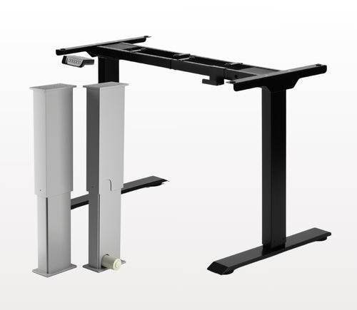
Kyllä, L-muotoinen seisomapöytä on suunnan suhteen joustava ja voidaan asentaa toiveidesi mukaan. Tässä on vaiheittainen artikkeli, joka selittää, miten tämä on mahdollista: FLT-05-käyttöohje
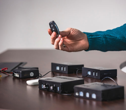
HUOM: Alla olevat vaiheet voivat vaihdella sen mukaan, mikä kaukosäädinmalli sinulla on. Seuraavat ohjeet on tehty vakio RT-11 -kaukosäätimelle. Asettaaksesi rungon enimmäiskorkeuden siirry haluamaasi korkeuteen ja seuraa alla olevia vaiheita:
- Paina M ja näet näytössä [5 -]
- Paina UP-painiketta ja huomaat, että [5 -] vilkkuu
- Pidä M-painiketta pohjassa, kunnes näytössä näkyy [999]
- Enimmäiskorkeus on nyt asetettu
Asettaaksesi rungon vähimmäiskorkeuden siirry haluamaasi korkeuteen ja seuraa alla olevia vaiheita:
- Paina M ja näet näytössä [5 -]
- Paina DOWN-painiketta ja huomaat, että [5 -] vilkkuu
- Pidä M-painiketta pohjassa, kunnes näytössä näkyy [000]
- Vähimmäiskorkeus on nyt asetettu
Palauttaaksesi rajat, toimi seuraavasti:
- Paina M, kunnes näytössä näkyy [5 -], ja vapauta
- Pidä M pohjassa, kunnes näet [555]
- Rajat on nollattu
HUOM: Alla olevat vaiheet voivat vaihdella sen mukaan, mikä kaukosäädin sinulla on. Seuraavat ohjeet on tehty vakio RT-11 -kaukosäätimelle.
Jos sinun täytyy pitää kaukosäätimen painikkeita pohjassa päästäksesi esiasetettuun korkeuteen, ohjainrasiasi toimii hetkellisessä ohjauksessa (momentary). Vaihtaaksesi kaukosäätimen pysyvään tilaan (non-momentary), toimi näin
- Varmista, ettei pöytäsi alla ole mitään, koska meidän on aloitettava nollausmenettely
- Paina ja pidä DOWN-painiketta, kunnes näytössä näkyy [ASr]
- Kun [ASr] näkyy, paina ja pidä [1]; voit nähdä kaksi arvoa:
a. 10.1 = Non-momentary Mode
b. 10.2 = Momentary Mode
- Viimeistele nollausmenettely pitämällä DOWN-painiketta, kunnes seisomapöytäsi laskeutuu hieman ja nousee takaisin.
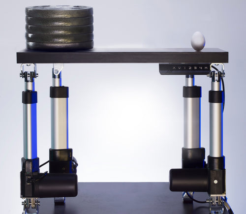
Seisomapöydissämme on 3 asetusta törmäyksen tunnistukselle, ja sen voi asettaa mieltymystesi mukaan. Jatka seuraavasti:
- Varmista, ettei pöytäsi alla ole mitään, koska meidän on aloitettava nollausmenettely
- Paina ja pidä DOWN-painiketta, kunnes näytössä näkyy [ASr]
- Kun [ASr] näkyy, paina ja pidä UP- [ ^ ] -painiketta; voit nähdä kolme arvoa:
a. 10.5 = 11 lbs
b. 10.6 = 22 lbs
c. 10.7 = 33 lbs
- Viimeistele nollausmenettely pitämällä DOWN-painiketta, kunnes seisomapöytäsi laskeutuu hieman ja nousee takaisin.
Tässä on joitakin vianmääritysvaiheita, jos näet minkä tahansa seuraavista virhekoodeista FLTCON-sarjan ohjainrasioilla varustetuissa rungoissa:
Tarkista virhekoodi täällä.
Jos kokemasi ongelma jatkuu näiden vaiheiden jälkeen, ota rohkeasti yhteyttä teknisiin tuoteinsinööreihimme numeroon 1-800-676-6123 tai lähetä meille sähköpostia osoitteeseen sales@progressiveautomations.com.