


We have data sheets, user manuals, 3D models, wiring diagrams and more in our Resources and Learning Center sections.

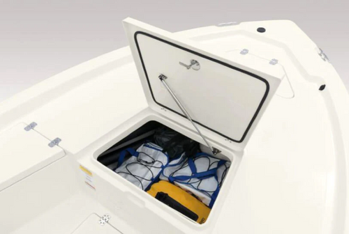
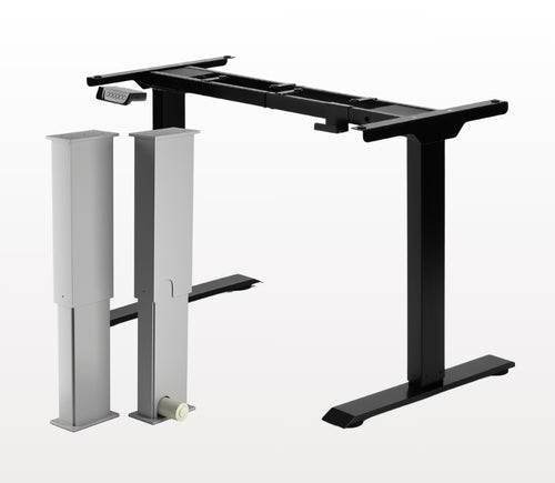
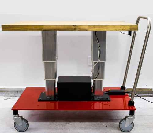
Da, L oblikovana stoječa miza omogoča poljubno usmeritev in jo je mogoče namestiti po vaši želji. Tukaj je članek s koraki, ki pojasnjuje, kako je to mogoče: Uporabniški priročnik FLT-05
OPOMBA: Spodnji koraki se lahko razlikujejo glede na model vaše daljinske enote. Naslednja navodila so pripravljena za standardni daljinski upravljalnik RT-11. Za nastavitev največje višine okvirja se premaknite na želeno višino in sledite spodnjim korakom:
- Pritisnite M in na zaslonu se bo prikazalo [5 -]
- Pritisnite gumb UP in opazili boste, da [5 -] utripa
- Držite gumb M, dokler na zaslonu ne vidite [999]
- Največja višina je zdaj nastavljena
Za nastavitev najmanjše višine okvirja se premaknite na želeno višino in sledite spodnjim korakom:
- Pritisnite M in na zaslonu se bo prikazalo [5 -]
- Pritisnite gumb DOWN in opazili boste, da [5 -] utripa
- Držite gumb M, dokler na zaslonu ne vidite [000]
- Najmanjša višina je zdaj nastavljena
Za ponastavitev omejitev sledite spodnjim korakom:
- Pritisnite M, na zaslonu se prikaže [5 -], in spustite
- Držite M, dokler ne vidite [555]
- Omejitve so bile ponastavljene
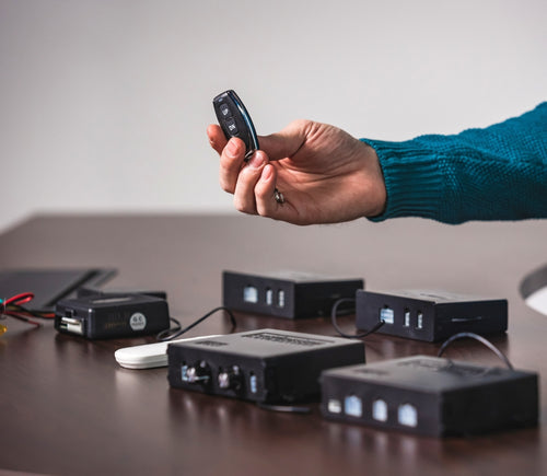
OPOMBA: Spodnji koraki se lahko razlikujejo glede na model vaše daljinske enote. Naslednja navodila so pripravljena za standardni daljinski upravljalnik RT-11.
Če morate držati gumbe na daljincu, da dosežete prednastavljeno višino, to pomeni, da je vaša krmilna škatla v načinu momentary. Da daljinec nastavite na način non-momentary, sledite spodnjim korakom
- Prepričajte se, da ni ničesar pod mizo, saj moramo vstopiti v postopek ponastavitve
- Pritisnite in držite gumb DOWN, dokler zaslon ne prikaže [ASr]
- Ko se prikaže [ASr], pritisnite in držite [1]; prikazani sta lahko dve vrednosti:
a. 10.1 = Non-momentary Mode
b. 10.2 = Momentary Mode
- Dokončajte postopek ponastavitve tako, da držite gumb DOWN, dokler se vaša stoječa miza rahlo ne spusti in ponovno dvigne.
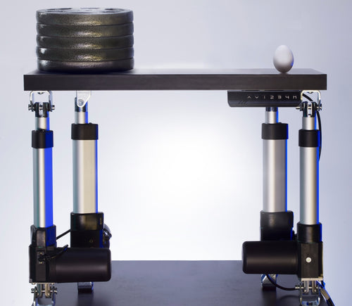
Naše stoječe mize imajo 3 nastavitve za zaznavanje trka, te pa lahko prilagodite svojim željam. Za nadaljevanje sledite spodnjim korakom:
- Prepričajte se, da ni ničesar pod mizo, saj moramo vstopiti v postopek ponastavitve
- Pritisnite in držite gumb DOWN, dokler zaslon ne prikaže [ASr]
- Ko se prikaže [ASr], pritisnite in držite gumb UP [ ^ ] in lahko vidite tri vrednosti:
a. 10.5 = 11 lbs
b. 10.6 = 22 lbs
c. 10.7 = 33 lbs
- Dokončajte postopek ponastavitve tako, da držite gumb DOWN, dokler se vaša stoječa miza rahlo ne spusti in ponovno dvigne.
Pripravili smo nekaj korakov za odpravljanje težav, če vidite katero od naslednjih kod napak na okvirjih s krmilnimi škatlami serije FLTCON:
Preverite kodo napake tukaj.
Če se težava po teh korakih še vedno pojavlja, se brez zadržkov obrnite na naše tehnične produktne inženirje na 1-800-676-6123, ali nam pošljite e-pošto na sales@progressiveautomations.com.