- Introduction au fonctionnement des actionneurs
- Mécanismes de rétroaction de position
- Types de systèmes de commande pour les actionneurs
- Rétroaction et correction d’erreurs
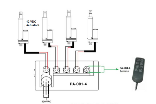
- Boîtiers de commande pour vérins linéaires
Introduction au fonctionnement des actionneurs
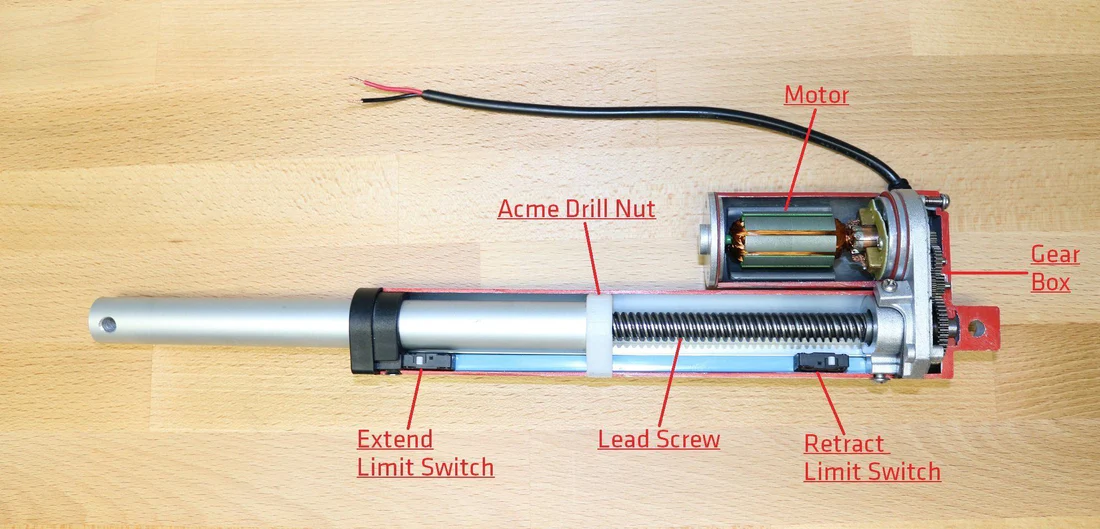
In electric linear actuators, electric current is used to produce rotational motion in an electric motor
that’s mechanically linked to a gearbox and utilizes a vis mère to cycle the actuator’s shaft attached to an ACME drill nut for linear motion. Control systems for actuators have developed significantly over the years, enhancing the versatility and functionality of these devices. Linear actuators can be operated through various means and control mechanisms including:
• Wireless controllers - offer users the convenience of remote control operation from a distance without the need for physical cables.
• Contrôleurs compatibles Wi‑Fi et Bluetooth - allow for integration into smart systems and access through mobile devices, providing user-friendly interfaces and the ability to adjust settings remotely and precisely.
These advancements in actuator technology and control systems have broadened the scope of their applications, making them indispensable in modern automated systems. Whether it's adjusting windows in véhicules, operating heavy duty équipements agricoles, or l’automatisation des appareils ménagers, actuators continue to be pivotal in translating electrical signals into physical action.

Comprendre les systèmes de commande pour les actionneurs
L'objectif principal de ces systèmes est de garantir un fonctionnement précis, efficace et fiable des actionneurs, conformément aux paramètres prédéfinis. L'importance des systèmes de commande dans le fonctionnement des actionneurs est capitale, notamment pour un contrôle précis et efficace des mouvements. Ces systèmes sont essentiels pour plusieurs raisons : 1. Précision : Les systèmes de contrôle permettent un réglage fin des mouvements des actionneurs afin d’obtenir des niveaux élevés de répétabilité et de précision. Ceci est essentiel dans les applications où un positionnement précis est critique, comme en chirurgie robotique ou en ingénierie aérospatiale. 2. Efficacité : En optimisant la réponse des actionneurs aux commandes, les systèmes de contrôle réduisent la consommation d’énergie et minimisent l’usure. Cela prolonge non seulement la durée de vie de l'actionneur, mais améliore également l'efficacité globale du système dans lequel il fonctionne.
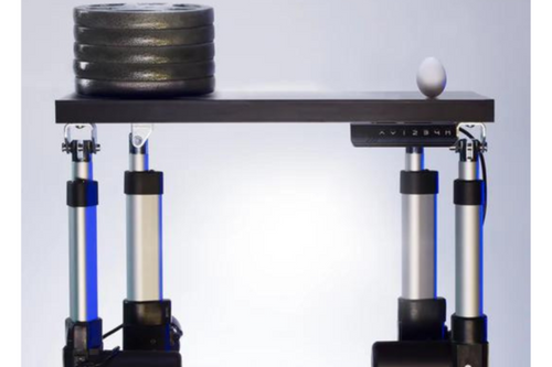
3. Adaptabilité : Les mécanismes de rétroaction peuvent ajuster en temps réel le comportement des actionneurs compatibles en analysant les données de position qu'ils reçoivent. Cette adaptabilité est essentielle dans les environnements dynamiques où les conditions évoluent rapidement, comme dans les processus de fabrication automatisés ou lorsque plusieurs actionneurs subissent une répartition de poids inégale.
5. Dispositifs de sécurité : Les dispositifs de sécurité programmés, tels que la protection contre les surcharges, contribuent à prévenir les dommages à un actionneur ou à l’application en interrompant le fonctionnement lorsque le boîtier de commande détecte une consommation de courant excessive. Une autre fonction de sécurité présente dans les boîtiers de commande est la protection contre la surchauffe. Celle-ci interrompt le fonctionnement après un certain nombre de cycles afin de garantir que le cycle de service de l'actionneur reste inférieur à ses valeurs nominales, évitant ainsi la surchauffe du moteur. Les systèmes de commande sont essentiels au fonctionnement des actionneurs. Ils leur confèrent l'intelligence et l'adaptabilité nécessaires pour assurer précision, efficacité, sécurité et un contrôle de mouvement performant. Leur rôle est primordial dans le domaine en pleine expansion des technologies d'automatisation, où la précision des mouvements est souvent la clé du succès opérationnel.
Composants et types de systèmes de commande
Composants clés d'un boîtier de commande de base
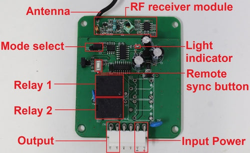
Dans un boîtier de commande de base conçu pour les actionneurs linéaires électriques, chaque composant joue un rôle crucial pour assurer un fonctionnement efficace. Voici une description détaillée de ces principaux composants, de leurs fonctions et de leur utilité :1. Relais : Les relais fonctionnent comme des interrupteurs qui commandent le circuit électrique haute puissance à l'aide d'un signal basse puissance. Pour les boîtiers de commande conçus pour gérer des actionneurs à deux fils, deux relais sont indispensables pour inverser la polarité de la tension appliquée aux deux fils de l'actionneur, ce qui modifie le sens du mouvement. Ceci permet une commande bidirectionnelle simple pour déployer et rétracter l'actionneur.
2. Canaux d'entrée : Les canaux d'entrée sont des interfaces par lesquelles le système de commande reçoit des signaux électriques provenant de sources externes, telles que des alimentations ou des télécommandes filaires. Les boîtiers de commande à retour de position peuvent également recevoir des données des capteurs de l'actionneur. Ces canaux traitent les entrées de l'utilisateur et/ou des capteurs afin de déterminer le mode de fonctionnement de l'actionneur. Ils sont donc essentiels pour initier et contrôler les mouvements de l'actionneur en fonction d'exigences spécifiques.
3. Canaux de sortie : Les canaux de sortie transmettent les signaux de commande du contrôleur à l'actionneur ou à d'autres composants, comme des relais. Les boîtiers de commande à retour de position peuvent également fournir un courant électrique pour alimenter les capteurs de l'actionneur. Ces canaux sont essentiels à l'exécution des commandes définies par le système de contrôle, influençant directement le comportement de l'actionneur.
4. Bouton de synchronisation à distance : Ce bouton permet de synchroniser le système de contrôle avec une télécommande. Il garantit la reconnaissance et le traitement des entrées de la télécommande par le système de contrôle, facilitant ainsi une utilisation pratique et flexible à distance.
5. Voyant lumineux : Les voyants lumineux fournissent un retour visuel sur l'état du système. Ils peuvent indiquer la mise sous/hors tension, les modes de fonctionnement, les erreurs ou la réception du signal, facilitant ainsi la surveillance et le dépannage du système sans outils de diagnostic complexes.
6. Sélection du mode : Cette fonction permet à l'utilisateur de basculer entre différents modes de fonctionnement du boîtier de commande, tels que les commandes momentanées ou non momentanées. En mode momentané, le bouton de la télécommande doit être maintenu enfoncé pour que l'appareil fonctionne. Dès que vous relâchez le bouton, l'appareil s'arrête. Le mode non momentané fonctionne comme un interrupteur qui reste dans sa dernière position jusqu'à ce qu'il soit modifié, qu'il soit enfoncé ou non. Cela signifie qu'une fois activé, l'appareil continue de fonctionner jusqu'à ce que l'interrupteur soit éteint manuellement.
7. Antenne : L'antenne fait partie des boîtiers de commande dotés d'un système de communication sans fil. Elle sert à améliorer la portée et la qualité du signal entre le système de commande et les dispositifs de télécommande, ou entre systèmes interconnectés. Elle est essentielle pour maintenir une communication fiable dans les environnements où le câblage direct est impossible ou indésirable.
8. Module récepteur RF : Ce module reçoit les signaux radiofréquences émis par les télécommandes sans fil. Il décode ces signaux en commandes exploitables par le système de commande. Le module récepteur RF est indispensable aux systèmes de commande sans fil, permettant ainsi la commande à distance de l'actionneur sans contact physique. Ensemble, ces composants forment un système de commande complet pour les actionneurs à deux fils. Chacun remplit une fonction spécifique qui contribue à l'efficacité globale du fonctionnement de l'actionneur. Ce système permet non seulement un contrôle précis des mouvements de l'actionneur, mais améliore également l'interface utilisateur et l'interaction, le rendant adaptable à une large gamme d'applications.
Mécanismes de rétroaction de position
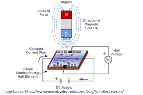
Capteurs à effet Hall
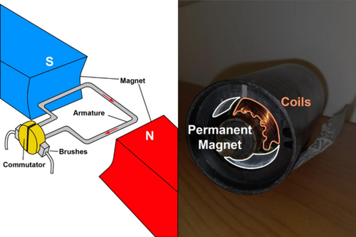
The Hall Effect theory, Edwin Hall (who discovered the Hall Effect), stated that whenever a magnetic field is applied in a direction perpendicular to the flow of electric current in a conductor, a voltage difference is induced. This voltage can be used to detect whether a hall effect sensor is in the proximity of a magnet.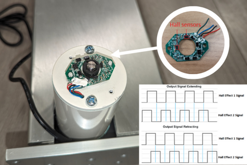
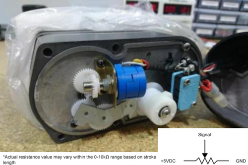
Potentiomètres
A potentiometer provides a variable resistance that is proportional to the position of the actuator. Gears are often linked between the potentiometer’s knob and the actuator’s rotating motor. As the actuator moves, the resistance value changes, which can be measured and converted into position data. This information is then used by a control system to make fine adjustments to the actuator's position, enhancing accuracy.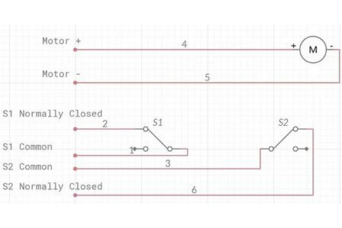
Rétroaction par interrupteurs de fin de course
The purpose of limit switch feedback signals is to allow a system to determine whether the actuator has physically tripped the internal limit switches. This kind of feedback is simple and useful for applications that mainly just require information on whether the actuator has reached the fully extended or fully retracted positions.Types de systèmes de commande pour les actionneurs
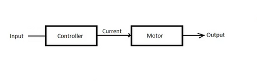
One example of a simple open-loop system includes a momentary rocker switch wired to a linear actuator. This requires an operator to physically press and hold the switch for the actuator to continue cycling and letting go of the switch before the actuator has reached the end of travel will result in the actuator stopping motion mid-way.
The choice of control system and its components significantly impacts actuators' functionality and performance optimization. By integrating effective feedback mechanisms and selecting the appropriate control system type, actuators can be optimized for a wide range of applications, ensuring both precision and reliability in their operation.
Rétroaction et correction d’erreurs
Variables corrigées par les systèmes de commande
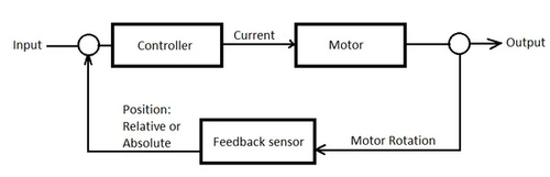
1. Position : Control systems help ensure that an actuator reaches and maintains the desired position accurately by comparing the user’s position to the actual position reading from the positional feedback sensors. Examples include when standing desk users press a controller’s button to have actuators travel to a specific preset memory position to adjust their workspace from the seated to standing height.
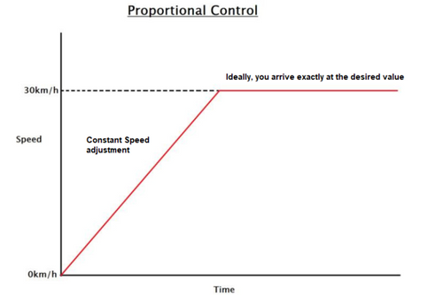
2. Vitesse : Reading positional feedback and dividing the distance traveled by how much time had passed will result in travel speed. Some control systems allow for adjustable speed settings through PWM (Pulse Width Modulation), enabling the actuator to move at different speeds based on the application's requirements. This is useful in applications where varying speeds are necessary such as for actuators driving the motion of flight simulators.
3. Force : Certain control systems can regulate the amount of force exerted by actuators, ensuring that it operates within safe limits and prevents damage to the system or surrounding components. By measuring the electric current draw, control systems can gauge approximately how much force is being exerted by linear actuators. This feature is useful for linear actuators that open and close windows to shut off power and stop applying force in case a person's hand or obstacle is blocking the path of travel.
Types de stratégies de commande

Choisir le bon système de commande
• Indice de protection (IP)
• Compatibilité
• Budget
1. Indice de protection (IP) : Évaluez les exigences environnementales spécifiques de votre application afin de déterminer le type de système de commande nécessaire. Le boîtier de commande PA-33, par exemple, possède un indice de protection IP65 contre la poussière et l’eau. Un indice de protection IP65 ou supérieur est recommandé pour les systèmes de commande exposés aux éléments extérieurs tels que la pluie, la poussière et les débris. 2. Compatibilité : Assurez-vous que le système de commande est compatible avec les vérins linéaires électriques que vous avez choisis ou utilisez actuellement, afin de garantir une intégration fluide. Vérifiez si votre actionneur dispose de protocoles de communication/rétroaction de position compatibles avec les contrôleurs envisagés. Par exemple, les actionneurs servo de micro-précision PA-12-T (TTL/PWM) et PA-12-R (RS-485) offrent une commande de position précise avec une exactitude de position jusqu’à 100 µm et nécessitent des protocoles de communication avancés pour de telles performances. Un autre point à considérer est la compatibilité entre le type de moteur de votre actionneur et un système de commande. Des moteurs sans balais à fonctionnement continu, comme ceux que l’on trouve dans nos actionneurs PA-14 sur commande, nécessitent des boîtiers de commande compatibles avec leur fonctionnement, tels que le boîtier LC-241. To see which of our control boxes and actuators are compatible with each other, check out our control box comparison and compatibility charts linked below: https://7717445.fs1.hubspotusercontent-na1.net/hubfs/7717445/PDF%20Manuals/Desk%20Accessories/Control%20Boxes%20Compatibility%20Chart%202023.pdf https://7717445.fs1.hubspotusercontent-na1.net/hubfs/7717445/PDF%20Manuals/Desk%20Accessories/Control%20Boxes%20Comparison%20Chart-1.pdf 3. Budget : Déterminez s’il existe des contraintes budgétaires pour le projet et choisissez un système de commande offrant le meilleur rapport valeur/coût tout en répondant à vos exigences de performance. Par exemple, des projets d’intérieur simples ne nécessitant pas une grande précision fonctionneront sans problème en câblant un interrupteur à bascule basique, sans haut indice de protection, pour piloter un mini-vérin linéaire 2 fils à prix abordable.
Boîtiers de commande de type effet Hall
Lisez notre blog sur les applications des boîtiers de commande FLTCON pour plus d'informations.