Nella guida di oggi vedremo come determinare quanta forza sta applicando un attuatore lineare monitorando la quantità di corrente che sta utilizzando. Questa sarà una delle nostre guide più avanzate e richiederà operazioni più complesse di programmazione, calibrazione e configurazione. Tratteremo il monitoraggio dell’ingresso analogico e come sfruttarne le funzioni. Per questo progetto useremo un MegaMoto Plus, un attuatore lineare (stiamo usando il nostro attuatore mini PA-14), un Arduino Uno e un alimentatore di almeno 12V.

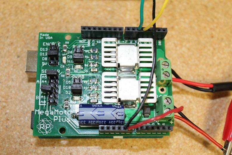
Per iniziare, dobbiamo eseguire i collegamenti per connettere tutto. Inizia inserendo il MegaMoto nell’Arduino: posiziona semplicemente il MegaMoto sopra l’Uno. Quindi collega un filo dal terminale BAT+ del MegaMoto al pin Vin dell’Uno.

Ora dobbiamo collegare i cavi degli attuatori lineari ai terminali A e B del MegaMoto e collegare l’alimentazione a 12V a BAT+ e GND a BAT-. Dovremo anche cablare due pulsanti di controllo collegandoli ciascuno tra un pin inutilizzato e GND. Consigliamo di collegare i pulsanti su una breadboard.

Ora è il momento di scrivere un po’ di codice con l’Arduino Uno. Vogliamo programmare i pulsanti in modo che possano controllare quando l’attuatore si estende e si ritrae. Il monitoraggio della corrente inizierà non appena l’attuatore si estende e questo ci permetterà di osservare se supera o meno il limite massimo di corrente. Se supera il limite, l’attuatore si fermerà automaticamente finché non deciderai di ritrarlo. Considerando che i motori all’interno degli attuatori hanno un forte picco di corrente quando vengono alimentati per la prima volta, il codice che inseriremo avrà un breve ritardo prima di iniziare a monitorare la corrente. Questo codice è in grado di leggere quando l’attuatore ha raggiunto i finecorsa, ossia quando la corrente scende a 0.
const int EnablePin = 8;
const int PWMPinA = 11;
const int PWMPinB = 3; // pins for Megamoto
const int buttonLeft = 4;
const int buttonRight = 5;//buttons to move the motor
const int CPin1 = A5;  // motor feedback

int leftlatch = LOW;
int rightlatch = LOW;//motor latches (used for code logic)
int hitLimits = 0;//start at 0
int hitLimitsmax = 10;//values to know if travel limits were reached

longlastfeedbacktime = 0; // must be long, else it overflows
int firstfeedbacktimedelay = 750; //first delay to ignore current spik
int feedbacktimedelay = 50; //delay between feedback cycles, how often you want the motor to be checked
currentTimefeedback = 0; // must be long, else it overflows
unceTime = 300; //amount to debounce buttons, lower values makes the buttons more sensitivelong lastButtonpress = 0; // timer for debouncing
long currentTimedebounce = 0;
int CRaw = 0;      // input value for current readings
int maxAmps = 0; // trip limit
bool dontExtend = false;
bool firstRun = true;
bool fullyRetracted = false;//program logic

void setup()
{
  Serial.begin(9600);
  pinMode(EnablePin, OUTPUT);
  pinMode(PWMPinA, OUTPUT);
  pinMode(PWMPinB, OUTPUT);//Set motor outputs
  pinMode(buttonLeft, INPUT);
  pinMode(buttonRight, INPUT);//buttons
  digitalWrite(buttonLeft, HIGH);
  digitalWrite(buttonRight, HIGH);//enable internal pullups
  pinMode(CPin1, INPUT);//set feedback input
  currentTimedebounce = millis();
  currentTimefeedback = 0;//Set initial times
  maxAmps = 15;// SET MAX CURRENT HERE
}//end setup

void loop()
{
  latchButtons();//check buttons, see if we need to move
  moveMotor();//check latches, move motor in or out
}//end main loop

void latchButtons()
{
  if (digitalRead(buttonLeft)==LOW)//left is forwards
 {
    currentTimedebounce = millis() - lastButtonpress;// check time since last press
    if (currentTimedebounce > debounceTime && dontExtend == false)//once you've tripped dontExtend, ignore all forwards presses
    {
      leftlatch = !leftlatch;// if motor is moving, stop, if stopped, start movingfirstRun = true;// set firstRun flag to ignore current spike
      fullyRetracted = false; // once you move forwards, you are not fully retracted
      lastButtonpress = millis();//store time of last button press
      return;
    }//end if
  }//end btnLEFT

  if (digitalRead(buttonRight)==LOW)//right is backwards
  {
    currentTimedebounce = millis() - lastButtonpress;// check time since last press
    if (currentTimedebounce > debounceTime)
    {
      rightlatch = !rightlatch;// if motor is moving, stop, if stopped, start moving
      firstRun = true;// set firstRun flag to ignore current spike
      lastButtonpress = millis();//store time of last button press
      return;
    }//end if
  }//end btnRIGHT
}//end latchButtons

void moveMotor()
{
  if (leftlatch == HIGH) motorForward(255); //speed = 0-255
  if (leftlatch == LOW) motorStop();
  if (rightlatch == HIGH) motorBack(255); //speed = 0-255
  if (rightlatch == LOW) motorStop();
}//end moveMotor

void motorForward(int speeed)
{
  while (dontExtend == false && leftlatch == HIGH)
  {
    digitalWrite(EnablePin, HIGH);
    analogWrite(PWMPinA, speeed);
    analogWrite(PWMPinB, 0);//move motor
    if (firstRun == true) delay(firstfeedbacktimedelay); // bigger delay to ignore current spike
    else delay(feedbacktimedelay); //small delay to get to speed
    getFeedback();
    firstRun = false;
    latchButtons();//check buttons again
  }//end while
}//end motorForward

void motorBack (int speeed)
{
  while (rightlatch == HIGH)
  {
    digitalWrite(EnablePin, HIGH);
    analogWrite(PWMPinA, 0);
    analogWrite(PWMPinB, speeed);//move motor
    if (firstRun == true) delay(firstfeedbacktimedelay);// bigger delay to ignore current spike
    else delay(feedbacktimedelay); //small delay to get to speed
    getFeedback();
    firstRun = false;
    latchButtons();//check buttons again
  }//end while
  dontExtend = false;//allow motor to extend again, after it has been retracted
}//end motorBack

void motorStop()
{
  analogWrite(PWMPinA, 0);
  analogWrite(PWMPinB, 0);
  digitalWrite(EnablePin, LOW);
  firstRun = true;//once the motor has stopped, reenable firstRun to account for startup current spikes
}//end stopMotor

void getFeedback()
{
  CRaw = analogRead(CPin1); // Read current
  if (CRaw == 0 && hitLimits < hitLimitsmax) hitLimits = hitLimits + 1;
  else hitLimits = 0; // check to see if the motor is at the limits and the current has stopped
  if (hitLimits == hitLimitsmax && rightlatch == HIGH)
  {
    rightlatch = LOW; // stop motor
    fullyRetracted = true;
  }//end if
  else if (hitLimits == hitLimitsmax && leftlatch == HIGH)
  {
    leftlatch = LOW;//stop motor
    hitLimits = 0;
  }//end if
  if (CRaw > maxAmps)
  {
    dontExtend = true;
    leftlatch = LOW; //stop if feedback is over maximum
  }//end if
  lastfeedbacktime = millis();//store previous time for receiving feedback
}//end getFeedback
Il nuovo e migliorato attuatore mini PA-01 (aggiornamento del PA-14) è il modello attuale che offriamo con una varietà di vantaggi aggiuntivi. Per un confronto, consulta le tabelle qui sotto e aggiorna con fiducia!
|
|
PA-01 |
PA-14 |
|
Opzioni di carico dinamico |
16, 28, 56, 112, 169, 225 lbs |
35, 50, 75, 110, 150 lbs |
|
Carico massimo |
225 lbs |
150 lbs |
|
Velocità massima |
3.54 "/sec |
2.00"/sec |
|
Grado di protezione IP |
IP65 |
IP54 |
|
Opzioni di corsa |
1" a 40" |
1" a 40" |
|
Feedback a effetto Hall |
Opzionale |
No |
Con questo codice di base monitorerai con successo il feedback del tuo attuatore lineare. In Parte II approfondiremo come funziona il codice e come modificarlo in base alle tue preferenze. Speriamo che questo post ti sia stato utile e resta sintonizzato per la Parte II nelle prossime settimane. Se desideri ordinare una delle unità che abbiamo utilizzato in questo esempio o vuoi saperne di più sui nostri prodotti, contattaci.