Sono disponibili diverse lunghezze di corsa dei modelli su richiesta, invia una mail a: sales@progressiveautomations.com
Questo esempio di codice utilizza MegaMoto Plus e un Arduino Uno per monitorare la Corrente di un Attuatore lineare; tuttavia, prodotti simili possono essere usati come sostituti.
/* Codice per monitorare l'assorbimento di Corrente dell'Attuatore e togliere alimentazione se
sale oltre una certa soglia.
Scritto da Progressive Automations
19 agosto 2015
Hardware:
- Schede di controllo RobotPower MegaMoto
- Arduino Uno
- 2 pulsanti
*/
const int EnablePin = 8;
const int PWMPinA = 11;
const int PWMPinB = 3; // pin per Megamoto
const int buttonLeft = 4;
const int buttonRight = 5;//pulsanti per muovere il Motore
const int CPin1 = A5; // Feedback del Motore
int leftlatch = LOW;
int rightlatch = LOW;//latch del Motore (usati per la logica del codice)
int hitLimits = 0;//inizia a 0
int hitLimitsmax = 10;//valori per sapere se sono stati raggiunti i limiti di Corsa
long lastfeedbacktime = 0; // deve essere long, altrimenti va in overflow
int firstfeedbacktimedelay = 750; // primo ritardo per ignorare il picco di Corrente
int feedbacktimedelay = 50; // ritardo tra i cicli di Feedback, quanto spesso vuoi che il Motore venga controllato
long currentTimefeedback = 0; // deve essere long, altrimenti va in overflow
int debounceTime = 300; // tempo per il debounce dei pulsanti; valori più bassi rendono i pulsanti più sensibili
long lastButtonpress = 0; // timer per il debounce
long currentTimedebounce = 0;
int CRaw = 0; // valore di ingresso per le letture di Corrente
int maxAmps = 0; // soglia di intervento
bool dontExtend = false;
bool firstRun = true;
bool fullyRetracted = false;//logica del programma
void setup()
{
Serial.begin(9600);
pinMode(EnablePin, OUTPUT);
pinMode(PWMPinA, OUTPUT);
pinMode(PWMPinB, OUTPUT);//Imposta le uscite del Motore
pinMode(buttonLeft, INPUT);
pinMode(buttonRight, INPUT);//pulsanti
digitalWrite(buttonLeft, HIGH);
digitalWrite(buttonRight, HIGH);//abilita le pull-up interne
pinMode(CPin1, INPUT);//imposta l'ingresso di Feedback
currentTimedebounce = millis();
currentTimefeedback = 0;//Imposta i tempi iniziali
maxAmps = 15;// IMPOSTA QUI LA CORRENTE MASSIMA
}//fine setup
void loop()
{
latchButtons();//controlla i pulsanti, verifica se dobbiamo muoverci
moveMotor();//controlla i latch, muovi il Motore avanti o indietro
}//fine main loop
void latchButtons()
{
if (digitalRead(buttonLeft)==LOW)//sinistra = avanti
{
currentTimedebounce = millis() - lastButtonpress;// controlla il tempo dall'ultima pressione
if (currentTimedebounce > debounceTime && dontExtend == false)//una volta attivato dontExtend, ignora tutte le pressioni in avanti
{
leftlatch = !leftlatch;// se il Motore è in movimento, fermalo; se è fermo, avvialo
firstRun = true;// imposta il flag firstRun per ignorare il picco di Corrente
fullyRetracted = false; // una volta che ti muovi in avanti, non sei completamente retratto
lastButtonpress = millis();//memorizza l'ora dell'ultima pressione del pulsante
return;
}//fine if
}//fine btnLEFT
if (digitalRead(buttonRight)==LOW)//destra = indietro
{
currentTimedebounce = millis() - lastButtonpress;// controlla il tempo dall'ultima pressione
if (currentTimedebounce > debounceTime)
{
rightlatch = !rightlatch;// se il Motore è in movimento, fermalo; se è fermo, avvialo
firstRun = true;// imposta il flag firstRun per ignorare il picco di Corrente
lastButtonpress = millis();//memorizza l'ora dell'ultima pressione del pulsante
return; }//fine if
}//fine btnRIGHT
}//fine latchButtons
void moveMotor()
{
if (leftlatch == HIGH) motorForward(255); //Velocità = 0-255
if (leftlatch == LOW) motorStop();
if (rightlatch == HIGH) motorBack(255); //Velocità = 0-255
if (rightlatch == LOW) motorStop();
}//fine moveMotor
void motorForward(int speeed)
{
while (dontExtend == false && leftlatch == HIGH)
{
digitalWrite(EnablePin, HIGH);
analogWrite(PWMPinA, speeed);
analogWrite(PWMPinB, 0);//muovi il Motore
if (firstRun == true) delay(firstfeedbacktimedelay); // ritardo maggiore per ignorare il picco di Corrente
else delay(feedbacktimedelay); //breve ritardo per raggiungere la Velocità
getFeedback();
firstRun = false;
latchButtons();//controlla di nuovo i pulsanti
}//fine while
}//fine motorForward
void motorBack (int speeed)
{
while (rightlatch == HIGH)
{
digitalWrite(EnablePin, HIGH);
analogWrite(PWMPinA, 0);
analogWrite(PWMPinB, speeed);//muovi il Motore
if (firstRun == true) delay(firstfeedbacktimedelay);// ritardo maggiore per ignorare il picco di Corrente
else delay(feedbacktimedelay); //breve ritardo per raggiungere la Velocità
getFeedback();
firstRun = false;
latchButtons();//controlla di nuovo i pulsanti
}//fine while
dontExtend = false;//consenti di nuovo l'estensione del Motore, dopo che è stato retratto
}//fine motorBack
void motorStop()
{
analogWrite(PWMPinA, 0);
analogWrite(PWMPinB, 0);
digitalWrite(EnablePin, LOW);
firstRun = true;//una volta che il Motore si è fermato, riabilita firstRun per tenere conto dei picchi di Corrente all'avvio
}//fine stopMotor
void getFeedback()
{
CRaw = analogRead(CPin1); // Leggi la Corrente
if (CRaw == 0 && hitLimits < hitLimitsmax) hitLimits = hitLimits + 1;
else hitLimits = 0; // verifica se il Motore è ai limiti e la Corrente si è fermata
if (hitLimits == hitLimitsmax && rightlatch == HIGH)
{
rightlatch = LOW; // ferma il Motore
fullyRetracted = true;
}//fine if
else if (hitLimits == hitLimitsmax && leftlatch == HIGH)
{
leftlatch = LOW;//ferma il Motore
hitLimits = 0;
}//fine if
if (CRaw > maxAmps)
{
dontExtend = true;
leftlatch = LOW; //ferma se il Feedback supera il massimo
}//fine if
lastfeedbacktime = millis();//memorizza l'ora precedente per la ricezione del Feedback
}//fine getFeedback
Questo esempio di codice mostra come controllare fino a 4 dei nostri attuatori lineari con Arduino Uno e la LC-82 MultiMoto Arduino Shield; tuttavia è possibile utilizzare prodotti simili in sostituzione. Questo codice è destinato esclusivamente all'uso con modelli di attuatori che rientrano nei limiti di corrente di ciascun canale del MultiMoto, come PA-14 e PA-14P.
/* Codice di esempio per controllare fino a 4 attuatori, utilizzando il driver Robot Power MultiMoto.
Hardware:
- Robot Power MultiMoto
- Arduino Uno
Cablaggio:
- Collegare gli attuatori alle connessioni M1, M2, M3, M4 sulla scheda MultiMoto.
- Collegare il negativo (nero) al collegamento destro, il positivo (rosso) a quello sinistro.
- Collegare un'alimentazione a 12 volt (minimo 1 A per motore a vuoto, 8 A per motore a pieno carico) ai terminali BAT. Assicurarsi che positivo e negativo siano posizionati nei punti corretti.
Codice modificato da Progressive Automations a partire dal codice di esempio fornito da Robot Power
<a href="http://www.robotpower.com/downloads/" rel="nofollow"> http://www.robotpower.com/downloads/</a>
Dimostrazione Robot Power MultiMoto v1.0
Questo software è rilasciato nel Pubblico Dominio
*/
// includere la libreria SPI:
#include <SPI.h>
// Pin slave select L9958 per SPI
#define SS_M4 14
#define SS_M3 13
#define SS_M2 12
#define SS_M1 11
// Pin di direzione L9958
#define DIR_M1 2
#define DIR_M2 3
#define DIR_M3 4
#define DIR_M4 7
// Pin PWM L9958
#define PWM_M1 9
#define PWM_M2 10 // Timer1
#define PWM_M3 5
#define PWM_M4 6 // Timer0
// Abilitazione L9958 per tutti e 4 i motori
#define ENABLE_MOTORS 8
int pwm1, pwm2, pwm3, pwm4;
boolean dir1, dir2, dir3, dir4;
void setup() {
unsigned int configWord;
// inserire qui il codice di setup, eseguito una sola volta:
pinMode(SS_M1, OUTPUT); digitalWrite(SS_M1, LOW); // HIGH = non selezionato
pinMode(SS_M2, OUTPUT); digitalWrite(SS_M2, LOW);
pinMode(SS_M3, OUTPUT); digitalWrite(SS_M3, LOW);
pinMode(SS_M4, OUTPUT); digitalWrite(SS_M4, LOW);
// Pin di direzione L9958
pinMode(DIR_M1, OUTPUT);
pinMode(DIR_M2, OUTPUT);
pinMode(DIR_M3, OUTPUT);
pinMode(DIR_M4, OUTPUT);
// Pin PWM L9958
pinMode(PWM_M1, OUTPUT); digitalWrite(PWM_M1, LOW);
pinMode(PWM_M2, OUTPUT); digitalWrite(PWM_M2, LOW); // Timer1
pinMode(PWM_M3, OUTPUT); digitalWrite(PWM_M3, LOW);
pinMode(PWM_M4, OUTPUT); digitalWrite(PWM_M4, LOW); // Timer0
// Abilitazione L9958 per tutti e 4 i motori
pinMode(ENABLE_MOTORS, OUTPUT);
digitalWrite(ENABLE_MOTORS, HIGH); // HIGH = disabilitato
/ /******* Configurare i chip L9958 *********
' Registro di configurazione L9958
' Bit
'0 - RES
'1 - DR - reset
'2 - CL_1 - limite di corrente
'3 - CL_2 - limite di corrente
'4 - RES
'5 - RES
'6 - RES
'7 - RES
'8 - VSR - velocità di variazione della tensione (1 abilita il limite di variazione, 0 disabilita)
'9 - ISR - velocità di variazione della corrente (1 abilita il limite di variazione, 0 disabilita)
'10 - ISR_DIS - disabilita la variazione della corrente
'11 - OL_ON - abilita rilevamento di carico aperto
'12 - RES
'13 - RES
'14 - 0 - sempre zero
'15 - 0 - sempre zero
*/ // impostare il limite di corrente massimo e disabilitare il limite alla variazione ISR
configWord = 0b0000010000001100;
SPI.begin();
SPI.setBitOrder(LSBFIRST);
SPI.setDataMode(SPI_MODE1); // polarità del clock = bassa, fase = alta
// Motore 1
digitalWrite(SS_M1, LOW);
SPI.transfer(lowByte(configWord));
SPI.transfer(highByte(configWord));
digitalWrite(SS_M1, HIGH);
// Motore 2
digitalWrite(SS_M2, LOW);
SPI.transfer(lowByte(configWord));
SPI.transfer(highByte(configWord));
digitalWrite(SS_M2, HIGH);
// Motore 3
digitalWrite(SS_M3, LOW);
SPI.transfer(lowByte(configWord));
SPI.transfer(highByte(configWord));
digitalWrite(SS_M3, HIGH);
// Motore 4
digitalWrite(SS_M4, LOW);
SPI.transfer(lowByte(configWord));
SPI.transfer(highByte(configWord));
digitalWrite(SS_M4, HIGH);
//Impostare inizialmente l'attuatore per ritrarre a velocità 0 per sicurezza
dir1 = 0; dir2 = 0; dir3 = 0; dir4 = 0; // Imposta direzione
pwm1 = 0; pwm2 = 0; pwm3 = 0; pwm4 = 0; // Imposta velocità (0-255)
digitalWrite(ENABLE_MOTORS, LOW);// LOW = abilitato
} // Fine setup
void loop() {
dir1 = 1;
pwm1 = 255; // imposta direzione e velocità
digitalWrite(DIR_M1, dir1);
analogWrite(PWM_M1, pwm1); // scrivi sui pin
dir2 = 0;
pwm2 = 128;
digitalWrite(DIR_M2, dir2);
analogWrite(PWM_M2, pwm2);
dir3 = 1;
pwm3 = 255;
digitalWrite(DIR_M3, dir3);
analogWrite(PWM_M3, pwm3);
dir4 = 0;
pwm4 = 128;
digitalWrite(DIR_M4, dir4);
analogWrite(PWM_M4, pwm4);
delay(5000); // attendi dopo che tutti e quattro i motori sono stati impostati
dir1 = 0;
pwm1 = 128;
digitalWrite(DIR_M1, dir1);
analogWrite(PWM_M1, pwm1);
dir2 = 1;
pwm2 = 255;
digitalWrite(DIR_M2, dir2);
analogWrite(PWM_M2, pwm2);
dir3 = 0;
pwm3 = 128;
digitalWrite(DIR_M3, dir3);
analogWrite(PWM_M3, pwm3);
dir4 = 1;
pwm4 = 255;
digitalWrite(DIR_M4, dir4);
analogWrite(PWM_M4, pwm4);
delay(5000);
}//fine void loop
Questo esempio di codice serve per combinare il regolatore di Velocità Wasp a canale singolo con l'Arduino Uno per controllare il movimento di un Attuatore lineare, tuttavia, prodotti simili possono essere usati come sostituti.
/*Codice di esempio per il Robot Power Wasp.
Questo ESC è controllato tramite segnali RC, con impulsi
compresi tra 1000 e 2000 microsecondi.
Il loop principale di questo programma mantiene l'Attuatore fermo per 1 secondo, estende per 2 secondi,
si ferma per 1 secondo, retrae per 2 secondi e ripete.
Modificato da Progressive Automations, utilizzando il codice di esempio originale "Sweep" dalle
librerie di esempio di Arduino.
Hardware:
- 1 Controller Wasp
- Arduino Uno
Cablaggio:
Lato controllo:
- Collega rosso/nero a +5v e GND
- Collega il filo giallo al tuo pin di segnale sull'Arduino (in questo esempio, pin 9)
Lato alimentazione:
- Collega il +/- dell'alimentatore del Motore alle connessioni +/- sul Wasp
- Collega il +/- dell'Attuatore alle restanti due connessioni
Questo esempio di codice è di pubblico dominio.
*/
#include <servo.h>
Servo myservo; // crea un oggetto servo per controllare un servo
// sulla maggior parte delle schede si possono creare fino a dodici oggetti servo
int pos = 0; // variabile per memorizzare la posizione del servo
void setup()
{
myservo.attach(9); // collega il servo sul pin 9 all'oggetto servo
}
void loop()
{
myservo.writeMicroseconds(1500); // segnale di stop
delay(1000); //1 secondo
myservo.writeMicroseconds(2000); // segnale di Velocità massima in avanti
delay(2000); //2 secondi
myservo.writeMicroseconds(1500); // segnale di stop
delay(1000); // 1 secondo
myservo.writeMicroseconds(1000); // segnale di Velocità massima in retro
delay(2000); //2 secondi
}
Questo esempio di codice utilizza i nostri relè e un Arduino Uno per controllare un attuatore lineare; tuttavia è possibile utilizzare prodotti simili in sostituzione. Puoi leggere il nostro articolo del blog completo per maggiori dettagli.
const int forwards = 7;
const int backwards = 6;//assegna il pin INx del relè al pin Arduino
void setup() {
pinMode(forwards, OUTPUT);//imposta il relè come uscita
pinMode(backwards, OUTPUT);//imposta il relè come uscita
}
void loop() {
digitalWrite(forwards, LOW);
digitalWrite(backwards, HIGH);//Attiva il relè in una direzione; devono essere diversi per muovere il motore
delay(2000); // attendi 2 secondi
digitalWrite(forwards, HIGH);
digitalWrite(backwards, HIGH);//Disattiva entrambi i relè per frenare il motore
delay(2000);// attendi 2 secondi
digitalWrite(forwards, HIGH);
digitalWrite(backwards, LOW);//Attiva il relè nell'altra direzione; devono essere diversi per muovere il motore
delay(2000);// attendi 2 secondi
digitalWrite(forwards, HIGH);
digitalWrite(backwards, HIGH);//Disattiva entrambi i relè per frenare il motore
delay(2000);// attendi 2 secondi
}
Questo esempio di codice utilizza la nostra LC-80, un Arduino Uno, qualsiasi attuatore lineare e un'alimentazione; tuttavia è possibile utilizzare prodotti simili in sostituzione. Puoi trovare maggiori dettagli sul codice e sul suo funzionamento nel nostro articolo del blog.
//Usa i ponticelli sulla scheda per selezionare quali pin verranno utilizzati
int EnablePin1 = 13;
int PWMPinA1 = 11;
int PWMPinB1 = 3;
int extendtime = 10 * 1000; // 10 secondi, moltiplicato per 1000 per convertire in millisecondi
int retracttime = 10 * 1000; // 10 secondi, moltiplicato per 1000 per convertire in millisecondi
int timetorun = 300 * 1000; // 300 secondi, moltiplicato per 1000 per convertire in millisecondi
int duty;
int elapsedTime;
boolean keepMoving;
void setup() {
Serial.begin(9600);
pinMode(EnablePin1, OUTPUT);//Abilita la scheda
pinMode(PWMPinA1, OUTPUT);
pinMode(PWMPinB1, OUTPUT);//Imposta le uscite del motore
elapsedTime = 0; // Imposta il tempo a 0
keepMoving = true; //Il sistema si muoverà
}//fine setup
void loop() {
if (keepMoving)
{
digitalWrite(EnablePin1, HIGH); // abilita il motore
pushActuator();
delay(extendtime);
stopActuator();
delay(10);//breve ritardo prima della ritrazione
pullActuator();
delay(retracttime);
stopActuator();
elapsedTime = millis();//quanto tempo è passato?
if (elapsedTime > timetorun) {//se sono passati 300 secondi, fermarsi
Serial.print("Il tempo trascorso supera il tempo massimo di funzionamento. Tempo massimo: ");
Serial.println(timetorun);
keepMoving = false;
}
}//fine if
}//fine loop principale
void stopActuator() {
analogWrite(PWMPinA1, 0);
analogWrite(PWMPinB1, 0); // velocità 0-255
}
void pushActuator() {
analogWrite(PWMPinA1, 255);
analogWrite(PWMPinB1, 0); // velocità 0-255
}
void pullActuator() {
analogWrite(PWMPinA1, 0);
analogWrite(PWMPinB1, 255);//velocità 0-255
}
Questo programma può essere usato per estendere e retrarre continuamente la corsa di un attuatore lineare.
SETUP LOOP CODE
void setup() {
Serial.begin(9600); // inizializza la comunicazione seriale a 9600 bit al secondo
pinMode(out_lim, INPUT_PULLUP); // configura il pin 45 come pin di ingresso
pinMode(in_lim, INPUT_PULLUP); // configura il pin 53 come pin di ingresso
pinMode(run_f, OUTPUT); // configura il pin 25 come pin di uscita
pinMode(run_r, OUTPUT); // configura il pin 30 come pin di uscita
retract(); // ritrae la corsa all'avvio
delay(500);
}
void extend() // questa funzione abilita il motore
{
digitalWrite(run_f, LOW);
digitalWrite(run_r, HIGH);
}
void retract() // questa funzione inverte la direzione del motore
{
digitalWrite(run_f, LOW);
digitalWrite(run_r, LOW);
}
void run_stop() // questa funzione disabilita il motore
{
digitalWrite(run_f, HIGH);
digitalWrite(run_r, HIGH);
}
void loop() {
int out_lim_state = digitalRead(out_lim); // legge i finecorsa e ne salva il valore
int in_lim_state = digitalRead(in_lim);
Serial.print("outer limit switch value "), Serial.println(out_lim_state); // 0 -> il finecorsa è premuto
Serial.print("inner limit switch value "), Serial.println(in_lim_state); // 1 -> il finecorsa non è premuto
if (out_lim_state == 0 && in_lim_state == 1) // se il finecorsa esterno è premuto e quello interno no (completamente esteso)
{
retract(); // retrae la corsa
}
else if (out_lim_state == 1 && in_lim_state == 0) // se il finecorsa interno è premuto e quello esterno no (completamente retratto)
{
extend(); // estende la corsa
}
else // altrimenti non fare nulla
{
}
delay(5); // ritardo tra le letture per stabilità
}
We have data sheets, user manuals, 3D models, wiring diagrams and more in our Resources and Learning Center sections.
Depending on your application, there are different specification requirements you should consider when determining the linear actuator you need. These requirements include force, stroke, speed and mounting dimensions. For detailed actuator information, you can refer to either the datasheet or the specification table located on the selected actuator's product page. You can also contact us to speak with one of our expert engineers.
Duty cycle is the fraction of the working period in which a linear actuator can remain active. You can calculate the duty cycle of a linear actuator by using the following equation: Duty cycle (%) = (Time the linear actuator is active) / (Time for one working period)
For example: With a 25% duty cycle, an actuator can run for 5 minutes continuously before needing to rest for 15 minutes before operating.
Yes, our actuators can be seamless replacements for most applications. Please contact us if you are unsure of which actuator to opt for. You will need to know the voltage rating, force rating, and stroke length needed before we can give a recommendation for a replacement actuator.
Stroke is the travel distance of the extending rod. To find the stroke length you require, measure your application from the fully retracted position to the fully extended position. The difference will equal the stroke length you require.
We always recommend purchasing an actuator with a higher force rating than what the application requires. If unsure of your force requirements, this article may help you calculate this: How to Calculate Force to Find the Right Linear Actuator
Yes. However, it is important to have sufficient voltage and current to be applied to your actuator. Here is an article that may help you further: How to Choose the Right Power Supply for your Linear Actuator
To achieve synchronous motion control, you will require feedback. We offer feedback in the forms of internal limit switches, potentiometers, or hall effect sensors. The following article highlights some Progressive Automations' products that can be used for synchronized control: Controlling Multiple Linear Actuators at the Same Time
There are a number of reasons your linear actuator may be exerting a large amount of noise including over-force, side loading or potential water infiltration. However, it may also be the case that your actuator is simply a high-force rated actuator and therefore has a loud operating noise level. For information on how to possibly overcome this loud noise, please click here. If you are concerned there may be an issue with your actuator, please contact us.
Most of our linear actuators are available for customization. Please refer to your desired product’s datasheet to view the full capabilities of its custom options. Please note there will be a lead time of approximately 20 – 25 business days for production, excluding shipping time. There will also be an additional fee for each actuator that is modified. To find out more about custom orders, please contact us at 1800 – 676 – 6123.
Yes, this is possible. However, it does depend on the units you are currently using. To synchronize actuators, they require a form of feedback such as a potentiometer or hall effect sensors. For more information, see below some of our key content regarding linear actuator synchronization.
Presently, we do not have kits available. However, if you would like a recommendation on the compatibility of certain linear actuators with control systems, please email us at sales@progressiveautomations.com with the following information:
• Required voltage rating
• Required stroke length
• Required force rating
• Dimensional limitations of your application
• Description of your application into which the actuator(s) will be installed
Temperature may be a factor in the functionality of your linear actuator. Please ensure that you use your actuator within the specifications advised in the product datasheet. If you have a specific query related to an actuator and temperature, please contact us.
To do this, please ensure the specifications for your system are compatible with the actuator’s voltage and current ratings. If these specifications align with each other, this may be possible. Please contact us if you are unsure of which actuator to opt for.
To find this information please refer to your product’s data sheet. If your linear actuator was customized, please provide us with images of the product, including your sales order number (if possible) and email this information to sales@progressiveautomations.com
Please click here for a list of 3D CAD models available.
The control box you choose should be able to provide sufficient voltage and current rating to your actuator. If you are unsure of the specifications, please contact us.
Alternatively, you can also find compatible control boxes on your selected linear actuator's product page.
To do this, please ensure the specifications for your system are compatible with the control box’s voltage and current ratings. If these specifications align, this may be possible. if you are unsure of their compatibility, please contact us.
Yes, our PA-35 can control up to four linear actuators using an android/iOS device. For more information, read our detailed article on how to use our Wi-Fi control box and App.
No. However, we have a large variety of control boxes to choose from for each actuator. Alternatively, you may also use rocker switches as a form of motion control.
Yes, however you need to ensure your control box can provide sufficient current draw and compatible voltage. Otherwise, you risk damaging your actuator(s).
As we are primarily manufacturers and distributors, we have a limited amount of sample codes available. While we cannot provide specific coding for your application, we do have a growing list of sample Arduino codes. To access these sample codes, please click here.
We have a range of AC to DC power supplies to choose from in our catalog. As the majority of our actuators are powered via 12 VDC, a 12 VDC automotive battery is also a good solution. Please ensure the connected devices will provide sufficient current to your setup.
You can use your own power supply if it provides sufficient current draw and the right voltage to your system. Otherwise, you run the risk of damaging your actuator(s) and/or control box(es).
Yes, most of our power supplies can be converted up to 230 VAC. To browse our power supply range, click here.
While possible, we recommend using the control box that is included with the lifting column sets. These control boxes are specifically programmed for the lifting columns to work in synchronous motion and using a third-party controller may compromise this.
However, our new LG-11 offers many similar characteristics to the FLT-11 and has the option to be paired with the FLTCON series of control boxes and RT-11 remote for multiple units to travel in synchronous motion. We do have dual lifting column systems available such as FLT-06 or FLT-10 that could provide you with a minimum height of 22 inches from the ground.
All of our lifting columns include control boxes and remotes to control the units. If you would like to know more about the control boxes we use, please contact us.
The only customizable feature for our table/TV lifts is the input voltage. Please note that there will be a lead time of 20 – 25 business days for production of all custom orders.
Our motorized pop-up TV lift is capable of holding up to 60-inch TV’s and our drop-down TV lifts can cater for up to 95-inch TV’s. Click here to browse our TV lifts. For even more information, check out our guide to using TV lifts.
Our table lift weight capacities are dependent on the unit you are choosing. The minimum weight capacity in our line of table lifts is 180 lbs (equal to approximately 80 kg) for our FLT-01 Single Table Lift. The maximum weight capacity in our line of table lifts is 330 lbs (equal to approximately 150 kg) for our FLT-09 Table Lift Set and FLT-05 Table Lift Set.
No, all of our mounting brackets are sold separately to our linear actuators. However, we do produce compatible mounting brackets for each of our linear actuators. To find out which mounting bracket is suitable for your linear actuator, check out your selected actuator's product page (where it will be stated), or browse our mounting bracket catalog.
For this information, please refer to our wiring diagrams.
Please email us photos of your wiring setup so we can look into this further for you. One of our sales engineers will contact you as soon as possible.
Selecting the right electric actuator for your application is a key part of bringing it to life. You need to ensure it meets all your specifications and has the ability to do exactly what you want it to do. That is why we created this handy little flowchart for selecting a linear actuator. It is broken down into four sections, with each section showing different options for our actuators so you can clearly see how they differentiate from each other:
Backdriving is when an actuator starts sliding down under load, when it is either overloaded or when the actuator has been damaged. Watch the video.
What Does Dynamic and Static Load Ratings Mean?Dynamic load rating is the amount of weight an actuator can pull or push safely when being powered. Static load rating is the amount of weight the actuator can hold or withstand without back driving when it is not being powered. For example, let's just say you have an actuator installed on a window and the static load rating of the actuator is 100lbs, it could experience backdriving when there is a high wind event, which means there will be more pressure exerted on the actuator which would exceed the 100lbs load rating of the actuator.
What Is Lateral Loading?Lateral loading is when the actuator experiences forces from the lateral plane. Actuators are not meant to handle lateral forces at all so if it experiences any lateral forces, it will likely damage the actuator or bend the rod. So it's advised never to use lateral forces and always make sure the actuator is fully in line or in sync with your application, so it does not take any load other than the axial load. Watch the video.
Orders can be placed by one of the following ways:
Online: Use our online order process with options to pay by Credit Card or PayPal.
Phone: 1-800 – 676 – 6123
Yes, quantity discounts are applied if you purchase 7 or more of the same product. Quantity discount breakdowns are found on each product page. For more information on our discount structure please contact us.
We accept all major credit cards, PayPal, checks and wire transfers. For customers who wish to set up Net Term accounts, please email us to begin the application process.
For pricing in USD, please ensure you are visiting us from our US site. For pricing in CAD, please ensure you are visiting us from our Canadian site.
All products listed on the website are in stock and available for same-day shipping if your order is placed before 3pm PST. If one of our products is unavailable, we will contact you as soon as possible to inform you when the unit will be available.
Progressive Automations’ shipping fees are calculated based on a variety of factors including but not limited to: location, quantities, and the total weight of your order. Smaller items are shipped via parcel while larger items and bulk orders are shipped via a freight carrier service. We always endeavor to provide competitive shipping prices for all our customers.
Shipping methods are available through online and phone orders. If you wish to receive an estimated shipping cost of your order, this can be done by reviewing your final shopping cart.
We ship via multiple courier companies including FedEx, UPS, DHL and USPS. Your selected courier may vary based on your location. Any large orders are shipped using various freight forwarding companies.
Please contact us if you have any questions about these options or if you would like to ship using a different carrier/your own shipping account.
Canadian and USA customers will not pay or incur any duty taxes on their orders. Customers outside North America may be subject to duty and import fees. Please contact your local government authority for information on import fees and taxes.
Returns or exchanges are accepted within 30 days of receiving your order as long as the product has not been used, modified or damaged. For more information on our return policy please see our Shipping & Returns section.
Delivery to the continental United States may take between 4 to 10 business days. All other deliveries may take approximately 10 to 15 business days depending on your location. Please refer to our shipping policy for more information: Shipping & Returns
Unfortunately, Progressive Automations does not offer free shipping. However, you can get a quantity order discount starting at 7 of the same unit.
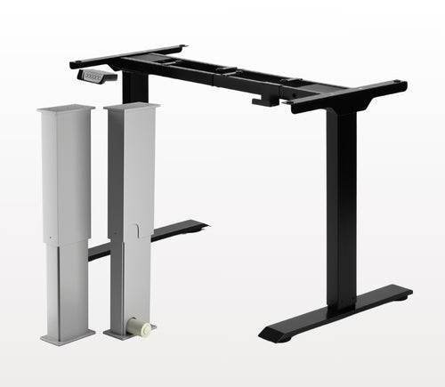
Sì, la scrivania ad L è reversibile e può essere installata secondo le tue preferenze. Ecco un articolo passo passo che spiega come fare: Manuale utente FLT-05
NOTA: I passaggi seguenti possono variare a seconda del modello di telecomando in tuo possesso. Le seguenti istruzioni sono per il telecomando standard RT-11. Per impostare l’altezza massima del telaio, porta la scrivania all’altezza desiderata e segui questi passaggi:
- Premere M e verificare che sul display compaia [5 -]
- Premere il pulsante UP e notare che [5 -] lampeggia
- Tenere premuto il pulsante M finché non compare [999] sul display
- L’altezza massima è stata impostata
Per impostare l’altezza minima del telaio, porta la scrivania all’altezza desiderata e segui questi passaggi:
- Premere M e verificare che sul display compaia [5 -]
- Premere il pulsante DOWN e notare che [5 -] lampeggia
- Tenere premuto il pulsante M finché non compare [000] sul display
- L’altezza minima è stata impostata
Per reimpostare i limiti, segui i passaggi seguenti:
- Premere M, verificare che sul display sia indicato [5 -], quindi rilasciare
- Tenere premuto M finché non vedi [555]
- I limiti sono stati reimpostati
NOTA: I passaggi seguenti possono variare a seconda del modello di telecomando in tuo possesso. Le seguenti istruzioni sono per il telecomando standard RT-11.
Se devi tenere premuti i pulsanti del telecomando per raggiungere l’altezza preimpostata, significa che la centralina è in modalità momentanea. Per impostare il telecomando in modalità non momentanea, segui i passaggi seguenti
- Assicurati che non ci sia nulla sotto la scrivania, perché dobbiamo avviare la procedura di reset
- Premi e tieni premuto il pulsante DOWN finché sul display non compare [ASr]
- Quando appare [ASr], premi e tieni premuto [1] e potresti vedere due valori:
a. 10.1 = Modalità non momentanea
b. 10.2 = Modalità momentanea
- Completa la procedura di reset tenendo premuto il pulsante DOWN finché la scrivania non si abbassa leggermente e poi risale.
Le nostre scrivanie regolabili hanno 3 impostazioni per il rilevamento delle collisioni, regolabili in base alle tue preferenze. Per procedere, segui i passaggi seguenti:
- Assicurati che non ci sia nulla sotto la scrivania perché dobbiamo avviare la procedura di reset
- Premi e tieni premuto il pulsante DOWN finché sul display non compare [ASr]
- Quando appare [ASr], premi e tieni premuto il pulsante UP [ ^ ] e potresti vedere tre valori:
a. 10.5 = 11 libbre
b. 10.6 = 22 libbre
c. 10.7 = 33 libbre
- Completa la procedura di reset tenendo premuto il pulsante DOWN finché la scrivania non si abbassa leggermente e poi risale.
Ecco alcuni passaggi di risoluzione dei problemi da eseguire se vedi uno dei seguenti codici di errore sui telai con centraline della serie FLTCON:
Controlla il codice di errore qui.
Se il problema persiste dopo aver seguito questi passaggi, contatta pure i nostri ingegneri tecnici di prodotto al 1-800-676-6123 oppure inviaci un’email a sales@progressiveautomations.com.