


This article is the first part of our “Linear Actuator Control" series. We will be discussing everything from the most basic control methods that utilize limit switches to accomplishing sequential control with the use of relays. In this first article, we will cover how to limit a linear actuator’s extension and retraction stroke using the AC-24 external limit switch.
- Closing or opening a door, window or attic hatch.
- Closing or opening a car hood or trunk.
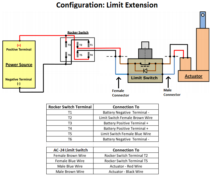
- Limiting extension.
- Limiting retraction.
- Limiting both extension and retraction.
Parts needed
- AC-24 external limit switch.
- Electric linear actuator.
- Crimp connectors or solder (optional).
Tools needed
- Wire stripper.
- Crimping tool or soldering iron (optional).
Wiring instructions
1. The first step when wiring the AC-24 external limit switch to a linear actuator is to label the wires on the AC-24. One would be “Male Connector" while the other is “Female Connector". After you have labeled the wires, you can cut both connectors on the AC-24 as well as the connector on the actuator.

2. The second step is to strip the ends of the wires bare on both the AC-24 and the actuator.

3. The third step is to connect the AC-24 to the actuator based on the wiring diagrams we have displayed below that correspond to the control method that you wish to achieve. We have a rocker switch in these illustrations but these limit switch wiring diagrams can be used with any control method, including our control boxes. Please take extra care to note the color codes of the components as they determine the direction of the actuator movement.
Limit switch wiring diagram


This concludes part 1 of our “Linear Actuator Control" series. We will be covering more methods of how to control your actuator in upcoming articles so stay tuned for more in the near future. Please feel free to contact us if you have any suggestions on what you would like us to cover in the future.
Read our blog at for all our latest blog entries, as well as our large selection of past articles and guides. If you have any questions or concerns regarding our products or would like to make a purchase do not hesitate to contact us today. Our experienced staff of engineers is here to help with whatever you may need.