
There may be cases when you want to move an object a longer distance than what the actuator's stroke length is. You can achieve this by using a telescoping actuator or you can use the physics of mechanical leveraging to your advantage. Common examples of this are the scissor lift or what our friend Mike Senna, the creator of the Wall-E Robot, did with his DIY Chicken Coop Automatic Door Opener.
Mechanical Leveraging
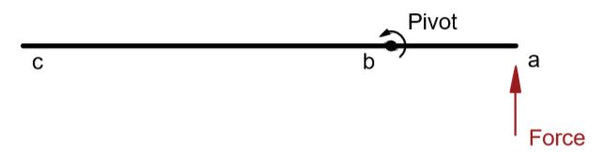
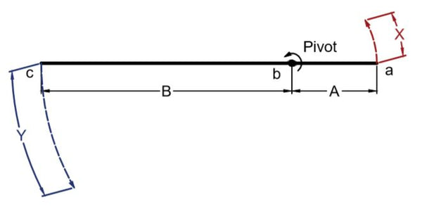
The physics behind these applications is using a ratio of distances from the pivot point on each side. As you can see in figure 1, the actuator is mounted at point ‘a’ with a fixed pivot at point ‘b’. By taking the ratio of ‘B’ and ‘A’, you achieve a ratio of ‘R’. This means that point ‘c’ will rotate ‘R’ times more than the stroke of the actuator. However, this will increase the amount of force required by the actuator and rotational speed of point ‘c’ by ‘R’ times. This is the principle behind how to leverage a linear actuator based on its stroke length and where you mount it.
DIY Chicken Coop Automatic Door Opener
Mike Senna's application uses the same principle discussed above and provides a great example of adding another member to convert the rotation of point ‘c’ to a linear motion. You can see in figure 2 that the top member rotates around the pivot point and the actuator pushing at point ‘a’.
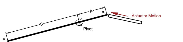
Figure 2: Top Member Rotating Around a Pivot at Point b
Mike knew that he needed the Chicken Coop door to open approximately 18 inches. In order to make the ratio ‘R’ equal to three to ensure that point ‘c’ would travel 18 inches with a 6-inch stroke, he placed the pivot point ¾ towards point ‘a’ (figure 3). Mike did this by positioning the arm so that there would be 3.5 inches on one side of the pivot point and 10.5 inches (3.5 inches x 3) on the other side.
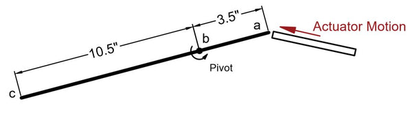
Figure 3: Top Member Rotating Around a Pivot at Point b with Dimension
After this, Mike added another member to transform the rotational motion to linear motion. He explains, “My solution was to add another arm whose purpose is to adjust for the arc as one end moves in an arc and the other end adjusts to a linear movement.” Figure 4 is a diagram made for his DIY Chicken Coop Automatic Door Opener project shown at various different positions along its travel. Note that the speed of the chicken coop door and force applied by the actuator will change throughout the travel. It was now a matter of adjusting the positioning to achieve the door travel he desired.
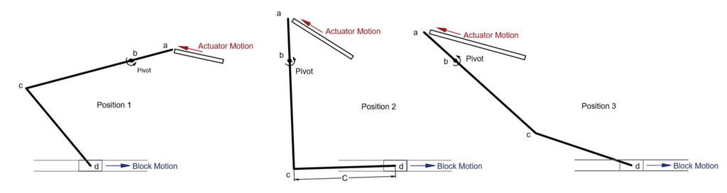
Figure 4: Chicken Coop Door at Three Different Positions
The Scissor Lift
The scissor lift is another application that uses this principle to achieve more linear motion with mechanical leveraging. To provide an example of how to leverage a linear actuator, a 3D model was created with an actuator for a scissor lift to simulate the larger movement of a platform with a relatively shorter movement of the actuator.
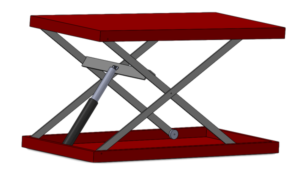
Figure 5: 3D Model of a Single-Stage Scissor Lift
As you can see in Figure 5, an actuator for a scissor lift with a relatively short stroke (8 inches in this case) was used to lift to a height of 36 inches. Scissor lifts work with the same principle where a body rotates around a pivot point and a mechanical advantage is created. However, instead of adding another member whose purpose is to simply translate the rotational motion of one end, the motion of the ends of members are restricted to a horizontal direction. This results in the direction of the force being only upwards.
What is interesting about the scissor lift is that if the actuator is mounted on the upper half, the lift will raise as the actuator extends. However, if the actuator is mounted on the lower half, the lift will raise as the actuator retracts. Also note that the closer the actuator is mounted to the mid-joint of the members, the more the lift will raise, but the actuator will require more force.
If you’re researching how to leverage a linear actuator in order to move an object a longer distance, a telescoping actuator or a DIY scissor lift mechanism will do the trick. For an actuator for a scissor lift or door mechanism, Progressive Automations stock a variety of models with varying strokes and forces to suit all your DIY needs.