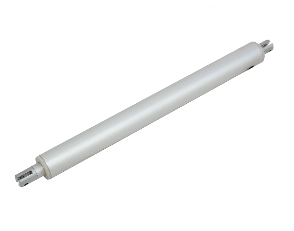
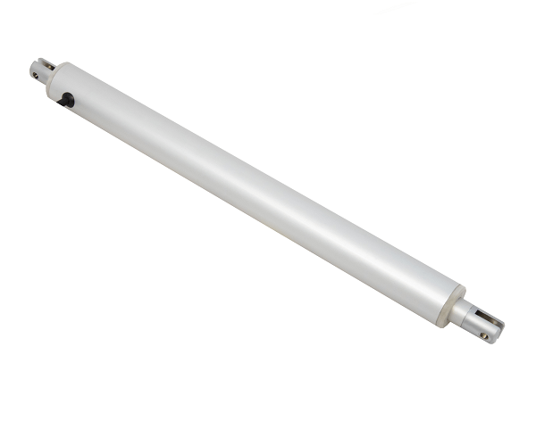
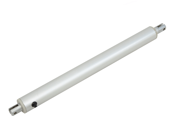
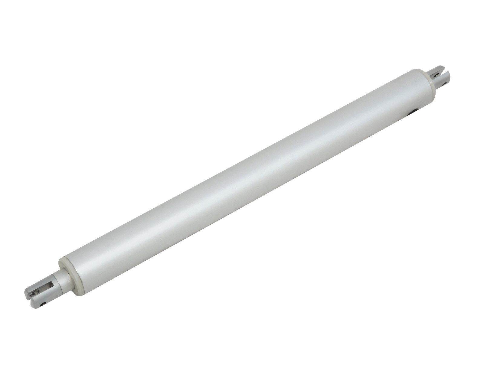
Actuador lineal de mini tubo
Actuador lineal de mini tubo


| Voltaje de entrada | 12 V CC, 24 V CC, 36 V CC, 48 V CC |
| Ataque | 1" a 24" (D30, D33), 2" a 32" (D42), 2" a 40" (D50) |
| Características | Ninguno |
| Comentario | Ninguno |
| Ciclo de trabajo | 20% (4 minutos de encendido, 16 minutos de apagado) |
| Protección contra la intemperie | IP54 |
| Protección contra sobrecarga | N / A |
| Temperatura de funcionamiento | -25ºC a 65ºC (-13ºF a 149ºF) |
| Ruido de funcionamiento | <52 dB |
| Interruptor de límite | Interno - No ajustable |
| Longitud del cable | 40" (cuctomizable) |
| Conector | Receptáculo Molex Mini Fit Jr de 2 pines |
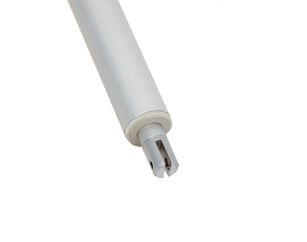
| Tamaño del orificio de montaje frontal | 0,20" |
| Tamaño del orificio de montaje trasero | 0,20" |
| Tipo de actuador | Mini tubo |
| Tipo de motor | Motor de CC con escobillas |
| Tipo de tornillo | Tornillo ACME |
| Material de la varilla de carrera | Aleación de aluminio |
| Material de la carcasa | Aleación de aluminio 6062 |
| Material del engranaje | Aleación de acero de pulvimetalurgia |
| Certificaciones | ESTE |
| Soportes de montaje compatibles | BRK-11 |
| Garantía | 18 meses |
Seguir un conjunto de normas es fundamental para que las empresas garanticen que sus productos y servicios alcancen un nivel de calidad que fomente la satisfacción del cliente. En Progressive Automations, aspiramos a ofrecer solo lo mejor a nuestros clientes y trabajamos en una mejora continua. Por ello, nos complace anunciar que ¡Progressive Automations ahora está certificada con ISO 9001:2015!
Calidad en la que puedes confiar – Más informaciónHojas de datos
PA-11-D30 Manual del usuario

3 ideas increíbles para actuadores lineales en aplicaciones de cocina
La revolución de la automatización, aclamada como la principal tendencia de la industria tecnológ...

Los sistemas robóticos ayudan a las personas con discapacidad
La robótica está allanando el camino para la automatización ; Incluso las sillas de ruedas ya no ...
Depending on your application, there are different specification requirements you should consider when determining the linear actuator you need. These requirements include force, stroke, speed and mounting dimensions. For detailed actuator information, you can refer to either the datasheet or the specification table located on the selected actuator's product page. You can also contact us to speak with one of our expert engineers.
Ciclo de trabajo es la fracción del periodo de trabajo durante la cual un actuador lineal puede permanecer activo. Puedes calcular el ciclo de trabajo de un actuador lineal usando la siguiente ecuación: Ciclo de trabajo (%) = (Tiempo que el actuador lineal está activo) / (Tiempo de un periodo de trabajo)
Por ejemplo: Con un ciclo de trabajo del 25 %, un actuador puede funcionar 5 minutos de forma continua antes de necesitar descansar 15 minutos antes de volver a operar.
Recorrido es la distancia de desplazamiento de la varilla extensible. Para encontrar la longitud de recorrido que necesitas, mide tu aplicación desde la posición completamente retraída hasta la posición completamente extendida. La diferencia será la longitud de recorrido que requieres.
Siempre recomendamos adquirir un actuador con una clasificación de fuerza superior a la que requiere la aplicación. Si no tienes claros tus requisitos de fuerza, este artículo puede ayudarte a calcularlos: Cómo calcular la fuerza para encontrar el actuador lineal adecuado
Sí, es posible. Sin embargo, depende de las unidades que estés utilizando. Para sincronizar actuadores, se requiere algún tipo de sensor de retroalimentación, como un potenciómetro o sensores de efecto Hall. Para más información, consulta a continuación algunos de nuestros contenidos clave sobre la sincronización de actuadores lineales.
La caja de control que elijas debe ser capaz de suministrar la tensión y la corriente nominal suficientes para tu actuador. Si no estás seguro de las especificaciones, por favor contáctanos.
Alternativamente, también puedes encontrar cajas de control compatibles en la página del producto del actuador lineal que hayas seleccionado.
Backdriving is when an actuator starts sliding down under load, when it is either overloaded or when the actuator has been damaged. Watch the video.
What Does Dynamic and Static Load Ratings Mean?Dynamic load rating is the amount of weight an actuator can pull or push safely when being powered. Static load rating is the amount of weight the actuator can hold or withstand without back driving when it is not being powered. For example, let's just say you have an actuator installed on a window and the static load rating of the actuator is 100 libras, it could experience backdriving when there is a high wind event, which means there will be more pressure exerted on the actuator which would exceed the 100 libras load rating of the actuator.
What Is Lateral Loading?Lateral loading is when the actuator experiences forces from the lateral plane. Actuators are not meant to handle lateral forces at all so if it experiences any lateral forces, it will likely damage the actuator or bend the rod. So it's advised never to use lateral forces and always make sure the actuator is fully in line or in sync with your application, so it does not take any load other than the axial load. Watch the video.