


Contamos con hojas de datos, manuales de usuario, modelos 3D, diagramas de cableado y más en nuestras secciones de Recursos y Centro de aprendizaje .

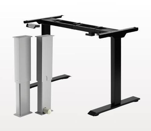
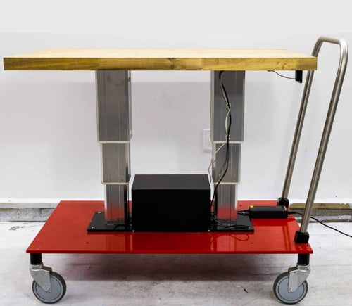
Sí, el escritorio de pie en forma de L admite ambas orientaciones y puede instalarse�0seg�fun tu preferencia. Aqu�d�ed tienes un art�edculo paso a paso que explica c�f3mo esto es posible:�a Manual del usuario FLT-05
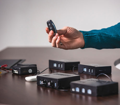
NOTA: Los pasos a continuaci�f3n pueden variar seg�fan el modelo de control remoto que tengas. Las siguientes instrucciones est�e1n hechas para el control RT-11 est�e1ndar. Para establecer la altura m�e1xima de tu bastidor, ve a la altura deseada y sigue los pasos a continuaci�f3n:
�09- Presiona M y ver�e1s [5 -] indicado en la pantalla �09
- Presiona el bot�f3n ARRIBA y notar�e1s que [5 -] parpadea �09
- Mant�e9n presionado el bot�f3n M hasta que veas [999] en la pantalla �09
- La altura m�e1xima ya se ha establecido
Para establecer la altura m�ednima de tu bastidor, ve a la altura deseada y sigue los pasos a continuaci�f3n:
�09- Presiona M y ver�e1s [5 -] indicado en la pantalla �09
- Presiona el bot�f3n ABAJO y notar�e1s que [5 -] parpadea �09
- Mant�e9n presionado el bot�f3n M hasta que veas [000] en la pantalla �09
- La altura m�ednima ya se ha establecido
Para restablecer los l�edmites, sigue los pasos a continuaci�f3n:
�09- Presiona M y ver�e1s [5 -] indicado en la pantalla y su�e9ltalo �09
- Mant�e9n presionado M hasta que veas [555] �09
- Los l�edmites se han restablecido
NOTA: Los pasos a continuaci�f3n pueden variar seg�fan el modelo de control remoto que tengas. Las siguientes instrucciones est�e1n hechas para el control RT-11 est�e1ndar.
Si debes mantener presionados los botones del control para llegar a tu altura preestablecida, significa que tu caja de control est�e1 en modo moment�e1neo. Para cambiar tu control a modo no moment�e1neo, sigue los pasos a continuaci�f3n
�09- Aseg�farate de que no haya nada debajo de tu escritorio, ya que debemos entrar en el procedimiento de restablecimiento �09
- Mant�e9n presionado el bot�f3n ABAJO hasta que la pantalla muestre [ASr] �09
- Una vez que aparezca [ASr], mant�e9n presionado [1] y podr�e1s ver dos valores:
a. 10,1 = Modo no moment�e1neo
b. 10,2 = Modo moment�e1neo
- Completa el procedimiento de restablecimiento manteniendo presionado el bot�f3n ABAJO hasta que tu escritorio de pie descienda y se eleve ligeramente.
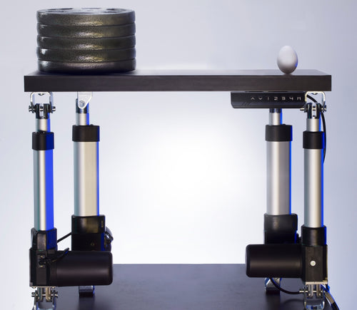
Nuestros escritorios de pie tienen 3 configuraciones para la detecci�f3n de colisiones, y puedes ajustarlas seg�fan tu preferencia. Para continuar, sigue los pasos a continuaci�f3n:
- Aseg�farate de que no haya nada debajo de tu escritorio ya que debemos entrar en el procedimiento de restablecimiento �09
- Mant�e9n presionado el bot�f3n ABAJO hasta que la pantalla muestre [ASr]
- Una vez que aparezca [ASr], mant�e9n presionado el bot�f3n ARRIBA [ ^ ] y podr�e1s ver tres valores:
a. 10,5 = 11 libras
b. 10,6 = 22 libras
c. 10,7 = 33 libras
- Completa el procedimiento de restablecimiento manteniendo presionado el bot�f3n ABAJO hasta que tu escritorio de pie descienda y se eleve ligeramente.
Tenemos algunos pasos de soluci�f3n de problemas para que sigas si ves cualquiera de los siguientes c�f3digos de error en los bastidores con cajas de control de la serie FLTCON:
Consulta el c�f3digo de error�aaqu�ed.
Si el problema que est�e1s experimentando persiste despu�e9s de seguir estos pasos, no dudes en comunicarte con nuestros ingenieros de producto t�e9cnico al 1-800-676-6123, o env�edanos un correo electr�f3nico a sales@progressiveautomations.com.