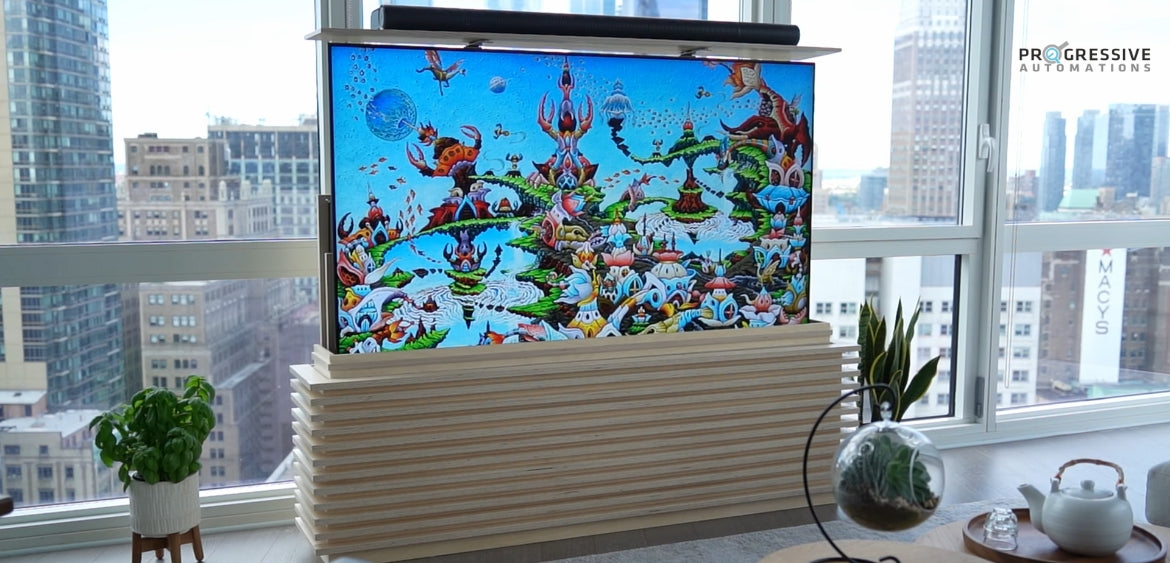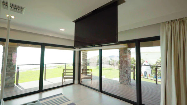
Having a TV lift can be useful for concealing and protecting a TV from unwanted scratches, dust, and accidental damage from pets or kids. The TV lift mechanism is also what allows for extra space saving by hiding your TV when it is no longer needed. Prior to the assembly of our TV lift, Chad from Broke OverLand had previously used our products for a Bed Lift System and Dinette Table for an LMTV camper which also helped him to save space in a small area. In this article, Chad covers the steps and procedures involved to install our TY-05 Drop-Down TV lift – although our motorized TY-05 can come with different stroke length options to better suit certain sized TVs, the overall steps for assembly and operation will still be similar for all TY-05 models.
Double Check the Parts

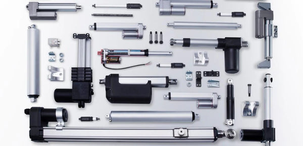
Before you build your own Drop-Down TV lift, we first want to make sure none of the pieces required are missing or lost, by verifying that all the parts are available. Below are the parts that would come with the purchase of every TY-05 TV lift:
- 1x Track Linear Actuator
- 1x Support Column
- 6x Bags of Hardware
- 2x Ceiling Cover Brackets
- 4x TV Mounting Brackets
- 2x TV Support Arms 30”
- 2x TV Support Arms 36”
- 1x Actuator Mounting Bracket
- 1x Control Box
- 1x Rocker Switch
- 1x External Limit Switch
- 1x Wireless Remote
- 1x Power Cable
- 1x Ceiling Cover
- 1x User manual (also available on our website)
Step 1: Mounting the TV Mounting Brackets

The first step begins as on page 5 of our user manual where M8 x 12 Phillips Countersunk Screws from bag P4 are used to mount the four TV Mounting Brackets to the backside of your TV. Some TVs have a deeper recess that these M8 x 12 Phillips Countersunk Screws will not reach, therefore, you will have to provide your own mounting hardware to attach the TV Mounting Brackets to the TV.

Tighten the brackets securely and use a tape measure to take note of how far up the brackets are away from the bottom of your television. For Chad, the center of his bracket is almost 11.5” away from the base. His brackets are also 8” apart in this example.
Step 2: Attaching the TV Support Arms and Support Column

Either the 30” or 36” TV Support Arm can be used depending on which width suits the installed TV. The Support Column has the three holes on the side for the top while the four holes on its face will be the bottom. From referring to the measurements prior, Chad will go 11” from the bottom to place his first TV Support Arm. The “U” of the Support Arm must be facing out when placed on top of the Support Column. Use the four M8 x 12 bolts, nuts, and washers from bag P3 to attach TV Support Arms to the Support Column. In this example, we will not need the nuts as we have captured nuts in our Support Arms. Tighten until secure with a six-millimeter Allen key. For the second TV Support Arm, Chad places it 8” apart to match his prior measurements before securing it into place.

Step 3: Securing Both Ceiling Cover Brackets to the Ceiling Cover

Use the four M5 x 12 screws, nuts, and washers from bag P2 to attach the Ceiling Cover to our Ceiling Cover Brackets. There are slots in the Ceiling Cover that allow the Ceiling Cover Brackets to slide through. The screws will go in from the bottom up. Our Ceiling Cover can be adjusted slightly in and out, however, Chad will have them pushed all the way out for now. Users can hold the nut with an eight-millimeter wrench on one side while tightening them on the other side with a medium point Phillips head screwdriver until fully secured.
Step 4: Mount the Ceiling Cover to the Support Column

Use the four M8 x 18 bolts, nuts, and washers from bag P1 to mount the assembled Ceiling Cover to the Support Column. The Support Column will be a U-channel facing back while the Ceiling Cover Brackets will be facing forward. The bolts slide in from the backside and a washer and nut will be placed on the front. Since the TV in this example is 11.5” to the bottom, Chad chooses to have the center 12” up so that the bottom of his TV will later be just off from the ceiling cover. Then, use a six-millimeter Allen key to securely tighten the bolt while holding the nut with a 13-millimeter or ½” wrench.
Step 5: Mounting the Track Linear Actuator

Use the Actuator Mounting Bracket, Clevis Pin and Cotter Pin from bag P6 to mount the top portion of your Track Linear Actuator. The bottom comes with an attached bracket that you will also need to mount with four wood screws that you will need to provide.

Step 6: Attaching Your Support Column to The Track Linear Actuator

For step 6, we recommend having at least two people. From bag P5, use the four M6 x 25 bolts and washers for the smaller holes on the outside and the two M10 x 25 bolts and washers for the middle holes to mount the assembled support column to the Track Linear Actuator. Install all the bolts before tightening to ensure proper alignment.
Step 7: Setting Up the Control System

When setting up the control system, you need to remove the retaining bracket and then remove the dust covers from input plugs one, two, and five of the Control Box. This will allow you to use the Wired Rocker Switch, Wired External Limit Switch, as well as the Track Linear Actuator. Our Track Linear Actuator will plug into slot one, the Rocker Switch connects to slot 2. The final slot 5 is for the External Limit Switch which is optional.

Once all the wiring has been completed, secure the connections with the retaining clip. Then, apply power to the Control Box through the Power Cable. When the green light on top of the Control Box is glowing, this indicates that you can now pair the Wireless Remote by holding the up and down arrows while simultaneously holding the button on the side of the Control Box for 10 seconds.

The Rocker Switch can be used without the Wireless Remote in case the Wireless Remote was misplaced or low on battery. Our optional External Limit Switch is for adjusting the height of travel from the TV lift. If you want the TV lift to only go to a certain point and stop because of the ceiling panel that you have mounted to your ceiling support bar, you can install the External Limit Switch so that the TV lift stops in a specific location. When you mount your Control Box near in your attic space, you will want to mount it so that your wires are not in the path of travel.
Step 8: Installing Your TV to the Lift

For this example, Chad made a provision in his ceiling space for the TV lift system to give a true feeling of what the setup will look like once fully installed. The final step is recommended to have two people to slide the TV onto the TV Support Arms. Now that your Drop-Down TV Lift is assembled, you can attach your TV Mounting Brackets to the TV Support Arms using the four M5 Thumb Screws from bag P4 to lock it in place.

There you have it, the complete installation of our Drop-Down TV lift! To get a 5% off for our TV lifts, use promo code BROKEOVERLAND at checkout! For the full installation video, feel free to check out Chad’s guide below:
IN SUMMARY
TV lifts can help protect a TV from unwanted scratches, dust, and other accidental damages. The assembly and operation of all our TY-05 TV lifts are very similar regardless of which size was selected and are quite feasible to assemble. By using a few tools and spending some time following our step-by-step guides, you can be one step closer to having your own DIY TV lift.
Thank you to Chad for sharing your project! We hope you continue to enjoy the new Drop-Down TV lift!
If you have any queries about our TV lifts or wish to discuss our products further, please do not hesitate in reaching out to us! We are experts in what we do and will be happy to assist in any way we can.
sales@progressiveautomations.com | 1-800-676-6123