


Disclaimer: The products mentioned in this article are no longer available in our inventory. This article has been maintained for reference purposes.
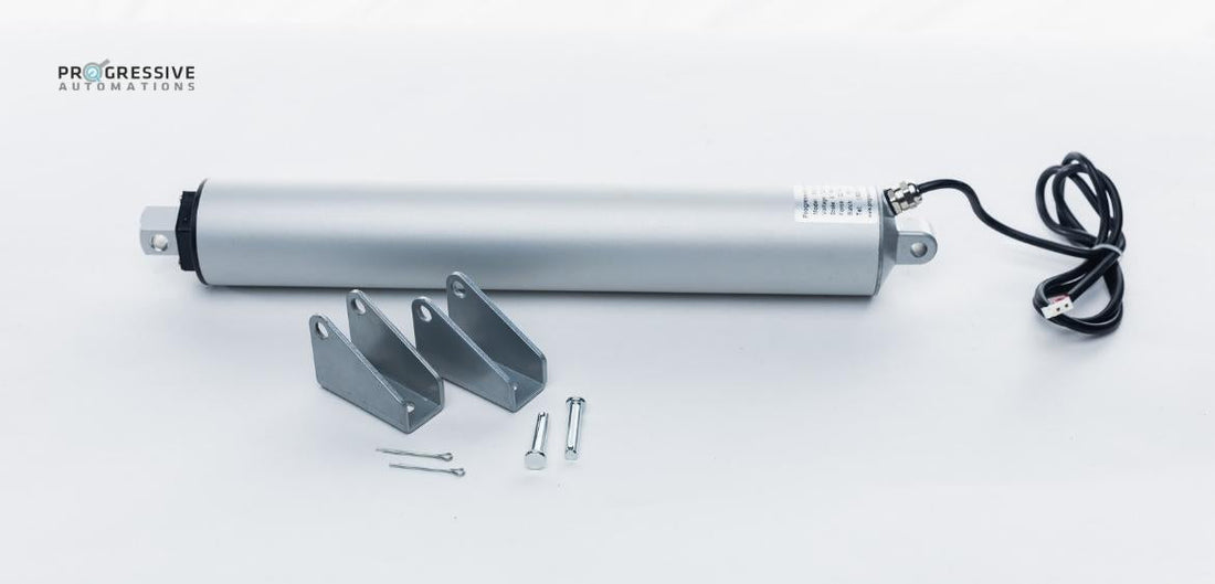
The PA-15 High-Speed Linear actuator is one of the fastest actuators in our lineup and due to its unique tubular design, one of our most compact products. Over time, normal wear or misuse takes its toll on the actuators and the motor can fail. Repairing an actuator may be cheaper than a replacement as the actuator repair cost is usually lower. Therefore, this article aims to guide you through how to repair an actuator!
You may be wondering how much does it cost to repair the PA-15 actuator? If you have a set of screwdrivers, hammer, pliers, and a soldering iron already, all it would be is the cost of the replacement motor itself. The cost of the motor can be found here. Please note that this article is mainly targeted towards people who are out of warranty or rejected from a warranty claim because of user error. Always check with us or the warranty information here to see if you can get the unit warranty replaced before trying this guide. Opening the actuator will result in the warranty being void! Please also make sure that the actuator is completely disconnected from any power source and not mounted in its application before operating on it.
Removing the Internal Assembly from the Casing
The first step in this motor replacement will be the removal of the internals from the tubular housing of the actuator. This section will detail the removal of the wire relief, endcap, and motor retaining ring.
Remove the Wire Relief
The wire relief is divided into two parts: the retaining nut and the relief itself. This section will show how to remove both parts.
Step 1:
Using an adjustable wrench or 14mm wrench, unbolt the wire relief retaining cap and slide it all the way back down the wire. The plastic wire relief should now be exposed.


Step 2:
With a counterclockwise twisting motion, turn and pull the relief until it is backed off completely to where it will not block the rest of the procedure.

Removing the Actuator End Cap, Motor Ring, and Shaft Seal
A quick word of warning, this part will start to get a bit greasy so please have some shop towels on hand and rubber gloves from here on out!
Step 1:
Using an adjustable wrench or 20mm wrench, insert it onto the motor cap mounting and turn counterclockwise. Be mindful to let the actuator’s wires turn with the cap to avoid unnecessary tearing of the wire. Once unscrewed, back the cap off so it is out of the way. Cut the cable at the shrink wrap and set aside cable external to the actuator.


Step 2:
Locate the two Allen screws preventing the motor retaining ring from spinning and back them off 2/3 of the way out of their threads.

Secure the actuator firmly in a vice or have someone hold else hold the actuator so it does not rotate. Using a flathead screwdriver and a hammer, hit the screw in a fashion where the ring will be persuaded counterclockwise. Once the ring is quite free, unscrew by hand the rest of the way out. When hitting the screw, please be mindful that too much/hard hammering can damage the thread of the screw.


Step 3:
Now, we will turn our attention to the shaft end of the actuator. Remove the three Phillips screws securing the shaft seal plate and remote the plate itself.

*picture of the seal with plate removed
Step 4:
Once the seal is exposed, push the shaft end towards the back of the actuator a little and then pull it back to where it was before, the shaft seal should now be exposed and available for removal. Set aside and keep clean.

Step 5:
Finally, using the stroke rod end of the actuator, push it in towards the back of the actuator and remove motor assembly completely from the tube housing. Keep track of the rubber seal at the end of the rod.


Removing the Rod and Limit Switch Assembly
This part will involve the soldering iron to separate the limit switch assembly and stroke rod from the motor. A drill with a chuck or a good set of vise-grips also will be needed.
Step 1:
Remove the stroke rod from the actuator by twisting it counterclockwise. A screwdriver through the stroke rod mounting hole may be needed to help.

Step 2:
Located at the tip of the actuator is a retaining ring with a rubber ring. Remove this retaining ring and rubber ring.


Depending on which position the actuator failed, you may or may not be able to see the screws that need to be accessed in the picture below. If you can access these 2 screws and remove them, please skip to step 4.
Step 3:
Using the vice-grips or drill, turn the ACME lead screw counterclockwise until the screws marked in the photo can be accessed.


Step 4:
Now unsolder the wires at the 2 points that are marked.

Step 5:
Remove the screws that were mentioned earlier. There are two little spacers that will come out at the same time as the screws and can go missing very easily.


Step 6:
Push the limit switch assembly away from the motor casing.

Removing the Leadscrew from the Motor and Installing it to New Motor
This part will show how to migrate the leadscrew of the actuator to the new motor. This step will require a hard surface like the back of a vice or similar block of steel.
Step 1:
Locate the pin that holds the lead screw with the motor.

Step 2:
Position the actuator onto your vice or similar block and use an appropriate punch to remove the pin. Be sure to retain the pin as it comes out.

Step 3:
Remove the old motor and position the new motor into the lead screw. Be sure to line up the hole on the motor shaft and leadscrew.

Step 4:
Install the pin through the two holes of the lead screw and the motor shaft. Make sure that the pin is flush or under the leadscrew on both sides.


Step 5:
Cut the loop of wire that comes off the top of the motor at the center.

Installing the Rod and Limit Switch Assembly
This step will show you how to reinstall the limit switch assembly and the stroke rod.
Step 1:
Bring the limit switch block close to the motor side and sneak the wires through the hole through the metal circle and limit switch block as described in the picture.

Step 2:
Replace the small plastic spacers into the metal circle and slide the limit switch block into place. Secure with the screws meant for this part.


Step 3:
Reinstall the rubber ring and its retaining ring to the end of the lead screw.

Wiring the Limit Switches
This part will detail the wiring of the limit switches so that the motor will stop at the ends of travel.
Step 1:
Take the wires that you snipped in Step 1 of the previous section and identify the one that can be pulled up and down easily. Do not pull either wire to the point that they enter the motor house on either end. Marked in the red circle is the loose wire and the green circle marks the tight wire.
Step 2:
Solder the wire that can be easily moved to the wire on the limit switch block side that has the jacketed wire. Once done, remove slack by pulling on this same wire that comes out the other end of the motor (should be very loose). Marked in the red circle is the loose wire and the green circle marks the tight wire.


Step 3:
Trim and solder the other wire that is not as loose (circled in green) as the one in the previous step to the bare wire on the limit switch block.

Test the Actuator
At this point, the actuator is ready to be tested with voltage. Apply the appropriate voltage for your actuator to the leads and test for proper extension and retraction of the actuator. If the actuator does not depower at the ends of the stroke, please check your limit switch wiring again.
Reinstalling the Actuator into the Housing
This step will show how to reinstall the actuator mechanism back into the housing that protects and gives the actuator strength.
Step 1:
Reinstall stroke rod by threading it into the shaft base. Tighten firmly.
Step 2:
Insert the entire mechanism into the housing of the actuator. Take care to line up the hexagonal stroke rod with the cap at the rod end of the housing.
Step 3:
Install retaining ring by threading it clockwise and torque with the hex screws. Thread hex screws back in and tighten firmly. Be sure to make sure the wires exit the housing through the retaining ring.


Step 4:
Reinstall the rubber seal at the end of the rod. Be sure to lube this seal with a grease that is safe for plastic and rubber. Reinstall the retaining plate for this seal afterward with the 3 Phillips head screws.


Step 5:
Reinstall motor cap.

Step 6:
Solder the section of wire exterior to the actuator to the wire ends of the motor. Be sure to attach red to black and black to red. This is the factory specification and will extend the rod with positive voltage on the red wire and retract the actuator with positive voltage to the black wire. Cover solder points with electrical tape or heat shrink.

Step 7:
Insert wire relief into housing and make sure that the relief grips onto the section that it gripped onto before. An indent in the wire will signify the point the wire relief should grip onto. Once in position, thread in the wire relief cap.


Procedure Complete!

Conclusion
In this article, we covered how to repair a PA-15 motor should the motor fail due to age or improper operation. While the procedure is really meant for someone who is electrically inclined, a mixture of soldering, mechanical aptitude, and general skill with a screwdriver will see you through this procedure.
If you have any questions during or before this procedure, please do not hesitate to contact one of our Technical Product Engineers for support!