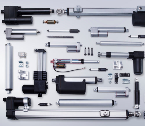
Verschillende slaglengtes van modellen zijn op verzoek beschikbaar, stuur ons een e-mail op: sales@progressiveautomations.com
Deze voorbeeldcode gebruikt MegaMoto Plus en een Arduino Uno om de stroom van een lineaire actuator te bewaken; vergelijkbare producten kunnen echter als vervanging worden gebruikt.
/* Code om de stroomafname (in ampère) van de actuator te bewaken en de voeding uit te schakelen als deze
boven een bepaalde waarde komt.
Geschreven door Progressive Automations
19 augustus 2015
Hardware:
- RobotPower MegaMoto-besturingsborden
- Arduino Uno
- 2 drukknoppen
*/
const int EnablePin = 8;
const int PWMPinA = 11;
const int PWMPinB = 3; // pinnen voor Megamoto
const int buttonLeft = 4;
const int buttonRight = 5;//knoppen om de motor te bewegen
const int CPin1 = A5; // motor-terugkoppeling
int leftlatch = LOW;
int rightlatch = LOW;//motorvergrendelingen (gebruikt voor codelogica)
int hitLimits = 0;//begin bij 0
int hitLimitsmax = 10;//waarden om te bepalen of de eindposities zijn bereikt
long lastfeedbacktime = 0; // moet long zijn, anders treedt overflow op
int firstfeedbacktimedelay = 750; //eerste vertraging om de stroompiek te negeren
int feedbacktimedelay = 50; //vertraging tussen terugkoppelingscycli; hoe vaak je de motor wilt controleren
long currentTimefeedback = 0; // moet long zijn, anders treedt overflow op
int debounceTime = 300; //tijd voor het debouncen van knoppen; lagere waarden maken de knoppen gevoeliger
long lastButtonpress = 0; // timer voor debouncen
long currentTimedebounce = 0;
int CRaw = 0; // invoerwaarde voor stroommetingen
int maxAmps = 0; // afschakelgrens
bool dontExtend = false;
bool firstRun = true;
bool fullyRetracted = false;//programmalogica
void setup()
{
Serial.begin(9600);
pinMode(EnablePin, OUTPUT);
pinMode(PWMPinA, OUTPUT);
pinMode(PWMPinB, OUTPUT);//Motoruitgangen instellen
pinMode(buttonLeft, INPUT);
pinMode(buttonRight, INPUT);//knoppen
digitalWrite(buttonLeft, HIGH);
digitalWrite(buttonRight, HIGH);//interne pullups inschakelen
pinMode(CPin1, INPUT);//terugkoppelingsinvoer instellen
currentTimedebounce = millis();
currentTimefeedback = 0;//Initiële tijden instellen
maxAmps = 15;// MAXIMALE STROOM HIER INSTELLEN
}//einde setup
void loop()
{
latchButtons();//knoppen controleren, kijken of we moeten bewegen
moveMotor();//vergrendelingen controleren, motor in- of uitschuiven
}//einde main loop
void latchButtons()
{
if (digitalRead(buttonLeft)==LOW)//links is vooruit
{
currentTimedebounce = millis() - lastButtonpress;// controleer tijd sinds laatste druk
if (currentTimedebounce > debounceTime && dontExtend == false)//als dontExtend is geactiveerd, alle vooruit‑drukken negeren
{
leftlatch = !leftlatch;// als de motor draait, stoppen; als hij stilstaat, starten
firstRun = true;// firstRun‑vlag zetten om stroompiek te negeren
fullyRetracted = false; // zodra je vooruit beweegt, ben je niet volledig ingetrokken
lastButtonpress = millis();//tijd van laatste knopdruk opslaan
return;
}//einde if
}//einde btnLEFT
if (digitalRead(buttonRight)==LOW)//rechts is achteruit
{
currentTimedebounce = millis() - lastButtonpress;// controleer tijd sinds laatste druk
if (currentTimedebounce > debounceTime)
{
rightlatch = !rightlatch;// als de motor draait, stoppen; als hij stilstaat, starten
firstRun = true;// firstRun‑vlag zetten om stroompiek te negeren
lastButtonpress = millis();//tijd van laatste knopdruk opslaan
return; }//einde if
}//einde btnRIGHT
}//einde latchButtons
void moveMotor()
{
if (leftlatch == HIGH) motorForward(255); //snelheid = 0-255
if (leftlatch == LOW) motorStop();
if (rightlatch == HIGH) motorBack(255); //snelheid = 0-255
if (rightlatch == LOW) motorStop();
}//einde moveMotor
void motorForward(int speeed)
{
while (dontExtend == false && leftlatch == HIGH)
{
digitalWrite(EnablePin, HIGH);
analogWrite(PWMPinA, speeed);
analogWrite(PWMPinB, 0);//motor bewegen
if (firstRun == true) delay(firstfeedbacktimedelay); // grotere vertraging om stroompiek te negeren
else delay(feedbacktimedelay); //kleine vertraging om op snelheid te komen
getFeedback();
firstRun = false;
latchButtons();//knoppen opnieuw controleren
}//einde while
}//einde motorForward
void motorBack (int speeed)
{
while (rightlatch == HIGH)
{
digitalWrite(EnablePin, HIGH);
analogWrite(PWMPinA, 0);
analogWrite(PWMPinB, speeed);//motor bewegen
if (firstRun == true) delay(firstfeedbacktimedelay);// grotere vertraging om stroompiek te negeren
else delay(feedbacktimedelay); //kleine vertraging om op snelheid te komen
getFeedback();
firstRun = false;
latchButtons();//knoppen opnieuw controleren
}//einde while
dontExtend = false;//motor weer laten uitschuiven nadat hij is ingetrokken
}//einde motorBack
void motorStop()
{
analogWrite(PWMPinA, 0);
analogWrite(PWMPinB, 0);
digitalWrite(EnablePin, LOW);
firstRun = true;//wanneer de motor gestopt is, firstRun opnieuw inschakelen om opstartstroompieken op te vangen
}//einde stopMotor
void getFeedback()
{
CRaw = analogRead(CPin1); // Stroom uitlezen
if (CRaw == 0 && hitLimits < hitLimitsmax) hitLimits = hitLimits + 1;
else hitLimits = 0; // controleren of de motor de eindposities heeft bereikt en de stroom is gestopt
if (hitLimits == hitLimitsmax && rightlatch == HIGH)
{
rightlatch = LOW; // motor stoppen
fullyRetracted = true;
}//einde if
else if (hitLimits == hitLimitsmax && leftlatch == HIGH)
{
leftlatch = LOW;//motor stoppen
hitLimits = 0;
}//einde if
if (CRaw > maxAmps)
{
dontExtend = true;
leftlatch = LOW; // stoppen als terugkoppeling boven maximum is
}//einde if
lastfeedbacktime = millis();//vorige tijd voor ontvangst van terugkoppeling opslaan
}//einde getFeedback
Deze voorbeeldcode laat zien hoe je tot 4 van onze lineaire actuatoren kunt aansturen met de Arduino Uno en LC-82 MultiMoto Arduino Shield; vergelijkbare producten kunnen echter als vervanging worden gebruikt. Deze code is alleen bedoeld voor actuatoren die binnen de stroombeperkingen per kanaal van de MultiMoto vallen, zoals de PA-14 en PA-14P.
/* Voorbeeldcode om tot 4 actuatoren te besturen met de Robot Power MultiMoto-driver.
Hardware:
- Robot Power MultiMoto
- Arduino Uno
Bedrading:
- Verbind actuatoren met de M1-, M2-, M3-, M4-aansluitingen op de MultiMoto-print.
- Verbind de negatieve (zwarte) met de rechteraansluiting, de positieve (rode) met de linker.
- Verbind een 12-volt bron (minimaal 1A per motor onbelast, 8A per motor volledig belast) met de BAT-klemmen. Zorg dat plus en min op de juiste plaatsen zijn aangesloten.
Code aangepast door Progressive Automations op basis van de voorbeeldcode van Robot Power
<a href="http://www.robotpower.com/downloads/" rel="nofollow"> http://www.robotpower.com/downloads/</a>
Robot Power MultiMoto v1.0 demo
Deze software is vrijgegeven in het Public Domain
*/
// neem de SPI-bibliotheek op:
#include <SPI.h>
// L9958 slave-select-pinnen voor SPI
#define SS_M4 14
#define SS_M3 13
#define SS_M2 12
#define SS_M1 11
// L9958 richtingpinnen
#define DIR_M1 2
#define DIR_M2 3
#define DIR_M3 4
#define DIR_M4 7
// L9958 PWM-pinnen
#define PWM_M1 9
#define PWM_M2 10 // Timer1
#define PWM_M3 5
#define PWM_M4 6 // Timer0
// L9958 Enable voor alle 4 motoren
#define ENABLE_MOTORS 8
int pwm1, pwm2, pwm3, pwm4;
boolean dir1, dir2, dir3, dir4;
void setup() {
unsigned int configWord;
// plaats je setup-code hier; wordt één keer uitgevoerd:
pinMode(SS_M1, OUTPUT); digitalWrite(SS_M1, LOW); // HIGH = niet geselecteerd
pinMode(SS_M2, OUTPUT); digitalWrite(SS_M2, LOW);
pinMode(SS_M3, OUTPUT); digitalWrite(SS_M3, LOW);
pinMode(SS_M4, OUTPUT); digitalWrite(SS_M4, LOW);
// L9958 richtingpinnen
pinMode(DIR_M1, OUTPUT);
pinMode(DIR_M2, OUTPUT);
pinMode(DIR_M3, OUTPUT);
pinMode(DIR_M4, OUTPUT);
// L9958 PWM-pinnen
pinMode(PWM_M1, OUTPUT); digitalWrite(PWM_M1, LOW);
pinMode(PWM_M2, OUTPUT); digitalWrite(PWM_M2, LOW); // Timer1
pinMode(PWM_M3, OUTPUT); digitalWrite(PWM_M3, LOW);
pinMode(PWM_M4, OUTPUT); digitalWrite(PWM_M4, LOW); // Timer0
// L9958 Enable voor alle 4 motoren
pinMode(ENABLE_MOTORS, OUTPUT);
digitalWrite(ENABLE_MOTORS, HIGH); // HIGH = uitgeschakeld
/ /******* L9958-chips instellen *********
' L9958 Config-register
' Bit
'0 - RES
'1 - DR - reset
'2 - CL_1 - stroomlimiet
'3 - CL_2 - stroomlimiet
'4 - RES
'5 - RES
'6 - RES
'7 - RES
'8 - VSR - spanningsslewrate (1 schakelt slewl imiet in, 0 schakelt uit)
'9 - ISR - stroomslewrate (1 schakelt slewlimiet in, 0 schakelt uit)
'10 - ISR_DIS - stroomslew uitschakelen
'11 - OL_ON - open-load inschakelen
'12 - RES
'13 - RES
'14 - 0 - altijd nul
'15 - 0 - altijd nul
*/ // instellen op maximale stroomlimiet en ISR-slew-begrenzing uitschakelen
configWord = 0b0000010000001100;
SPI.begin();
SPI.setBitOrder(LSBFIRST);
SPI.setDataMode(SPI_MODE1); // klokpol = laag, fase = hoog
// Motor 1
digitalWrite(SS_M1, LOW);
SPI.transfer(lowByte(configWord));
SPI.transfer(highByte(configWord));
digitalWrite(SS_M1, HIGH);
// Motor 2
digitalWrite(SS_M2, LOW);
SPI.transfer(lowByte(configWord));
SPI.transfer(highByte(configWord));
digitalWrite(SS_M2, HIGH);
// Motor 3
digitalWrite(SS_M3, LOW);
SPI.transfer(lowByte(configWord));
SPI.transfer(highByte(configWord));
digitalWrite(SS_M3, HIGH);
// Motor 4
digitalWrite(SS_M4, LOW);
SPI.transfer(lowByte(configWord));
SPI.transfer(highByte(configWord));
digitalWrite(SS_M4, HIGH);
//Initiële actuatorinstellingen op intrekken bij 0 snelheid zetten (veiligheidsmaatregel)
dir1 = 0; dir2 = 0; dir3 = 0; dir4 = 0; // Richting instellen
pwm1 = 0; pwm2 = 0; pwm3 = 0; pwm4 = 0; // Snelheid instellen (0-255)
digitalWrite(ENABLE_MOTORS, LOW);// LOW = ingeschakeld
} // Einde setup
void loop() {
dir1 = 1;
pwm1 = 255; //richting en snelheid instellen
digitalWrite(DIR_M1, dir1);
analogWrite(PWM_M1, pwm1); // naar pinnen schrijven
dir2 = 0;
pwm2 = 128;
digitalWrite(DIR_M2, dir2);
analogWrite(PWM_M2, pwm2);
dir3 = 1;
pwm3 = 255;
digitalWrite(DIR_M3, dir3);
analogWrite(PWM_M3, pwm3);
dir4 = 0;
pwm4 = 128;
digitalWrite(DIR_M4, dir4);
analogWrite(PWM_M4, pwm4);
delay(5000); // wachten zodra alle vier motoren zijn ingesteld
dir1 = 0;
pwm1 = 128;
digitalWrite(DIR_M1, dir1);
analogWrite(PWM_M1, pwm1);
dir2 = 1;
pwm2 = 255;
digitalWrite(DIR_M2, dir2);
analogWrite(PWM_M2, pwm2);
dir3 = 0;
pwm3 = 128;
digitalWrite(DIR_M3, dir3);
analogWrite(PWM_M3, pwm3);
dir4 = 1;
pwm4 = 255;
digitalWrite(DIR_M4, dir4);
analogWrite(PWM_M4, pwm4);
delay(5000);
}//einde void loop
Deze voorbeeldcode is bedoeld om de enkelkanaals Wasp‑snelheidsregelaar te combineren met de Arduino Uno om de beweging van een lineaire actuator te regelen; vergelijkbare producten kunnen echter als vervanging worden gebruikt.
/*Voorbeeldcode voor de Robot Power Wasp.
Deze ESC wordt bestuurd met RC-signalen met pulsen
van 1000 - 2000 microseconden.
De hoofdlus van dit programma houdt de actuator 1 seconde stil, schuift 2 seconden uit,
stopt 1 seconde, schuift 2 seconden in en herhaalt.
Aangepast door Progressive Automations, op basis van de oorspronkelijke voorbeeldcode "Sweep" uit de
Arduino-voorbeeldbibliotheken.
Hardware:
- 1 Wasp-controller
- Arduino Uno
Bedrading:
Besturingszijde:
- Verbind rood/zwart met +5v en GND
- Verbind de gele draad met je signaalpin op de Arduino (in dit voorbeeld, pin 9)
Vermogenszijde:
- Verbind de +/- van de stroomvoorziening van de motor met de +/- aansluitingen op de Wasp
- Verbind de +/- van de actuator met de overblijvende twee aansluitingen
Deze voorbeeldcode is publiek domein.
*/
#include <servo.h>
Servo myservo; // servo-object maken om een servo aan te sturen
// op de meeste borden kunnen twaalf servo-objecten worden gemaakt
int pos = 0; // variabele om de servo-positie op te slaan
void setup()
{
myservo.attach(9); // koppelt de servo op pin 9 aan het servo-object
}
void loop()
{
myservo.writeMicroseconds(1500); // stopsignaal
delay(1000); //1 seconde
myservo.writeMicroseconds(2000); // signaal volle snelheid vooruit
delay(2000); //2 seconden
myservo.writeMicroseconds(1500); // stopsignaal
delay(1000); // 1 seconde
myservo.writeMicroseconds(1000); // signaal volle snelheid achteruit
delay(2000); //2 seconden
}
Deze voorbeeldcode maakt gebruik van onze relais en Arduino Uno om een lineaire actuator te besturen; vergelijkbare producten kunnen echter als vervanging worden gebruikt. Je kunt ons volledige blogbericht lezen voor meer details.
const int forwards = 7;
const int backwards = 6;//relais-INx-pin koppelen aan Arduino-pin
void setup() {
pinMode(forwards, OUTPUT);//relais als uitgang instellen
pinMode(backwards, OUTPUT);//relais als uitgang instellen
}
void loop() {
digitalWrite(forwards, LOW);
digitalWrite(backwards, HIGH);//Relais in één richting activeren; de niveaus moeten verschillend zijn om de motor te laten bewegen
delay(2000); // 2 seconden wachten
digitalWrite(forwards, HIGH);
digitalWrite(backwards, HIGH);//Beide relais deactiveren om de motor te remmen
delay(2000);// 2 seconden wachten
digitalWrite(forwards, HIGH);
digitalWrite(backwards, LOW);//Relais in de andere richting activeren; de niveaus moeten verschillend zijn om de motor te laten bewegen
delay(2000);// 2 seconden wachten
digitalWrite(forwards, HIGH);
digitalWrite(backwards, HIGH);//Beide relais deactiveren om de motor te remmen
delay(2000);// 2 seconden wachten
}
Deze voorbeeldcode gebruikt onze LC-80, een Arduino Uno, elke lineaire actuator en een stroombron; vergelijkbare producten kunnen echter als vervanging worden gebruikt. Meer details over de code en wat deze doet vind je in onze blogpost.
//Use the jumpers on the board to select which pins will be used
int EnablePin1 = 13;
int PWMPinA1 = 11;
int PWMPinB1 = 3;
int extendtime = 10 * 1000; // 10 seconds, times 1000 to convert to milliseconds
int retracttime = 10 * 1000; // 10 seconds, times 1000 to convert to milliseconds
int timetorun = 300 * 1000; // 300 seconds, times 1000 to convert to milliseconds
int duty;
int elapsedTime;
boolean keepMoving;
void setup() {
Serial.begin(9600);
pinMode(EnablePin1, OUTPUT);//Enable the board
pinMode(PWMPinA1, OUTPUT);
pinMode(PWMPinB1, OUTPUT);//Set motor outputs
elapsedTime = 0; // Set time to 0
keepMoving = true; //The system will move
}//end setup
void loop() {
if (keepMoving)
{
digitalWrite(EnablePin1, HIGH); // enable the motor
pushActuator();
delay(extendtime);
stopActuator();
delay(10);//small delay before retracting
pullActuator();
delay(retracttime);
stopActuator();
elapsedTime = millis();//how long has it been?
if (elapsedTime > timetorun) {//if it's been 300 seconds, stop
Serial.print("Elapsed time is over max run time. Max run time: ");
Serial.println(timetorun);
keepMoving = false;
}
}//end if
}//end main loop
void stopActuator() {
analogWrite(PWMPinA1, 0);
analogWrite(PWMPinB1, 0); // speed 0-255
}
void pushActuator() {
analogWrite(PWMPinA1, 255);
analogWrite(PWMPinB1, 0); // speed 0-255
}
void pullActuator() {
analogWrite(PWMPinA1, 0);
analogWrite(PWMPinB1, 255);//speed 0-255
}
Met dit programma kunt u de slaglengte van een lineaire actuator continu in- en uitschuiven.
SETUP LOOP CODE
void setup() {
Serial.begin(9600); // initialize serial communication at 9600 bits per second
pinMode(out_lim, INPUT_PULLUP); // configures pin 45 as input pin
pinMode(in_lim, INPUT_PULLUP); // configures pin 53 as input pin
pinMode(run_f, OUTPUT); // configures pin 25 as output pin
pinMode(run_r, OUTPUT); // configures pin 30 as output pin
retract(); // retracts the stroke on startup
delay(500);
}
void extend() // this function enables the motor to run
{
digitalWrite(run_f, LOW);
digitalWrite(run_r, HIGH);
}
void retract() // this function reverses the direction of motor
{
digitalWrite(run_f, LOW);
digitalWrite(run_r, LOW);
}
void run_stop() // this function disables the motor
{
digitalWrite(run_f, HIGH);
digitalWrite(run_r, HIGH);
}
void loop() {
int out_lim_state = digitalRead(out_lim); // reads the limit switches and saves its value
int in_lim_state = digitalRead(in_lim);
Serial.print("outer limit switch value "), Serial.println(out_lim_state); // 0 -> limit switch is pressed
Serial.print("inner limit switch value "), Serial.println(in_lim_state); // 1 -> limit switch is not pressed
if (out_lim_state == 0 && in_lim_state == 1) // if outer limit switch is pressed and inner is not (extended all the way)
{
retract(); // retract the stroke
}
else if (out_lim_state == 1 && in_lim_state == 0) // if inner limit switch is pressed and outer is not (reracted all the way)
{
extend(); // extend the stroke
}
else // otherwise do nothing
{
}
delay(5); // delay in between reads for stability
}
We have data sheets, user manuals, 3D models, wiring diagrams and more in our Resources and Learning Center sections.
Depending on your application, there are different specification requirements you should consider when determining the linear actuator you need. These requirements include force, stroke, speed and mounting dimensions. For detailed actuator information, you can refer to either the datasheet or the specification table located on the selected actuator's product page. You can also contact us to speak with one of our expert engineers.
Duty cycle is the fraction of the working period in which a linear actuator can remain active. You can calculate the duty cycle of a linear actuator by using the following equation: Duty cycle (%) = (Time the linear actuator is active) / (Time for one working period)
For example: With a 25% duty cycle, an actuator can run for 5 minutes continuously before needing to rest for 15 minutes before operating.
Yes, our actuators can be seamless replacements for most applications. Please contact us if you are unsure of which actuator to opt for. You will need to know the voltage rating, force rating, and stroke length needed before we can give a recommendation for a replacement actuator.
Stroke is the travel distance of the extending rod. To find the stroke length you require, measure your application from the fully retracted position to the fully extended position. The difference will equal the stroke length you require.
We always recommend purchasing an actuator with a higher force rating than what the application requires. If unsure of your force requirements, this article may help you calculate this: How to Calculate Force to Find the Right Linear Actuator
Yes. However, it is important to have sufficient voltage and current to be applied to your actuator. Here is an article that may help you further: How to Choose the Right Power Supply for your Linear Actuator
To achieve synchronous motion control, you will require feedback. We offer feedback in the forms of internal limit switches, potentiometers, or hall effect sensors. The following article highlights some Progressive Automations' products that can be used for synchronized control: Controlling Multiple Linear Actuators at the Same Time
There are a number of reasons your linear actuator may be exerting a large amount of noise including over-force, side loading or potential water infiltration. However, it may also be the case that your actuator is simply a high-force rated actuator and therefore has a loud operating noise level. For information on how to possibly overcome this loud noise, please click here. If you are concerned there may be an issue with your actuator, please contact us.
Most of our linear actuators are available for customization. Please refer to your desired product’s datasheet to view the full capabilities of its custom options. Please note there will be a lead time of approximately 20 – 25 business days for production, excluding shipping time. There will also be an additional fee for each actuator that is modified. To find out more about custom orders, please contact us at 1800 – 676 – 6123.
Yes, this is possible. However, it does depend on the units you are currently using. To synchronize actuators, they require a form of feedback such as a potentiometer or hall effect sensors. For more information, see below some of our key content regarding linear actuator synchronization.
Presently, we do not have kits available. However, if you would like a recommendation on the compatibility of certain linear actuators with control systems, please email us at sales@progressiveautomations.com with the following information:
• Required voltage rating
• Required stroke length
• Required force rating
• Dimensional limitations of your application
• Description of your application into which the actuator(s) will be installed
Temperature may be a factor in the functionality of your linear actuator. Please ensure that you use your actuator within the specifications advised in the product datasheet. If you have a specific query related to an actuator and temperature, please contact us.
To do this, please ensure the specifications for your system are compatible with the actuator’s voltage and current ratings. If these specifications align with each other, this may be possible. Please contact us if you are unsure of which actuator to opt for.
To find this information please refer to your product’s data sheet. If your linear actuator was customized, please provide us with images of the product, including your sales order number (if possible) and email this information to sales@progressiveautomations.com
Please click here for a list of 3D CAD models available.
The control box you choose should be able to provide sufficient voltage and current rating to your actuator. If you are unsure of the specifications, please contact us.
Alternatively, you can also find compatible control boxes on your selected linear actuator's product page.
To do this, please ensure the specifications for your system are compatible with the control box’s voltage and current ratings. If these specifications align, this may be possible. if you are unsure of their compatibility, please contact us.
Yes, our PA-35 can control up to four linear actuators using an android/iOS device. For more information, read our detailed article on how to use our Wi-Fi control box and App.
No. However, we have a large variety of control boxes to choose from for each actuator. Alternatively, you may also use rocker switches as a form of motion control.
Yes, however you need to ensure your control box can provide sufficient current draw and compatible voltage. Otherwise, you risk damaging your actuator(s).
As we are primarily manufacturers and distributors, we have a limited amount of sample codes available. While we cannot provide specific coding for your application, we do have a growing list of sample Arduino codes. To access these sample codes, please click here.
We have a range of AC to DC power supplies to choose from in our catalog. As the majority of our actuators are powered via 12 VDC, a 12 VDC automotive battery is also a good solution. Please ensure the connected devices will provide sufficient current to your setup.
You can use your own power supply if it provides sufficient current draw and the right voltage to your system. Otherwise, you run the risk of damaging your actuator(s) and/or control box(es).
Yes, most of our power supplies can be converted up to 230 VAC. To browse our power supply range, click here.
While possible, we recommend using the control box that is included with the lifting column sets. These control boxes are specifically programmed for the lifting columns to work in synchronous motion and using a third-party controller may compromise this.
However, our new LG-11 offers many similar characteristics to the FLT-11 and has the option to be paired with the FLTCON series of control boxes and RT-11 remote for multiple units to travel in synchronous motion. We do have dual lifting column systems available such as FLT-06 or FLT-10 that could provide you with a minimum height of 22 inches from the ground.
All of our lifting columns include control boxes and remotes to control the units. If you would like to know more about the control boxes we use, please contact us.
The only customizable feature for our table/TV lifts is the input voltage. Please note that there will be a lead time of 20 – 25 business days for production of all custom orders.
Our motorized pop-up TV lift is capable of holding up to 60-inch TV’s and our drop-down TV lifts can cater for up to 95-inch TV’s. Click here to browse our TV lifts. For even more information, check out our guide to using TV lifts.
Our table lift weight capacities are dependent on the unit you are choosing. The minimum weight capacity in our line of table lifts is 180 lbs (equal to approximately 80 kg) for our FLT-01 Single Table Lift. The maximum weight capacity in our line of table lifts is 330 lbs (equal to approximately 150 kg) for our FLT-09 Table Lift Set and FLT-05 Table Lift Set.
No, all of our mounting brackets are sold separately to our linear actuators. However, we do produce compatible mounting brackets for each of our linear actuators. To find out which mounting bracket is suitable for your linear actuator, check out your selected actuator's product page (where it will be stated), or browse our mounting bracket catalog.
For this information, please refer to our wiring diagrams.
Please email us photos of your wiring setup so we can look into this further for you. One of our sales engineers will contact you as soon as possible.
Selecting the right electric actuator for your application is a key part of bringing it to life. You need to ensure it meets all your specifications and has the ability to do exactly what you want it to do. That is why we created this handy little flowchart for selecting a linear actuator. It is broken down into four sections, with each section showing different options for our actuators so you can clearly see how they differentiate from each other:
Backdriving is when an actuator starts sliding down under load, when it is either overloaded or when the actuator has been damaged. Watch the video.
What Does Dynamic and Static Load Ratings Mean?Dynamic load rating is the amount of weight an actuator can pull or push safely when being powered. Static load rating is the amount of weight the actuator can hold or withstand without back driving when it is not being powered. For example, let's just say you have an actuator installed on a window and the static load rating of the actuator is 100lbs, it could experience backdriving when there is a high wind event, which means there will be more pressure exerted on the actuator which would exceed the 100lbs load rating of the actuator.
What Is Lateral Loading?Lateral loading is when the actuator experiences forces from the lateral plane. Actuators are not meant to handle lateral forces at all so if it experiences any lateral forces, it will likely damage the actuator or bend the rod. So it's advised never to use lateral forces and always make sure the actuator is fully in line or in sync with your application, so it does not take any load other than the axial load. Watch the video.
Orders can be placed by one of the following ways:
Online: Use our online order process with options to pay by Credit Card or PayPal.
Phone: 1-800 – 676 – 6123
Yes, quantity discounts are applied if you purchase 7 or more of the same product. Quantity discount breakdowns are found on each product page. For more information on our discount structure please contact us.
We accept all major credit cards, PayPal, checks and wire transfers. For customers who wish to set up Net Term accounts, please email us to begin the application process.
For pricing in USD, please ensure you are visiting us from our US site. For pricing in CAD, please ensure you are visiting us from our Canadian site.
All products listed on the website are in stock and available for same-day shipping if your order is placed before 3pm PST. If one of our products is unavailable, we will contact you as soon as possible to inform you when the unit will be available.
Progressive Automations’ shipping fees are calculated based on a variety of factors including but not limited to: location, quantities, and the total weight of your order. Smaller items are shipped via parcel while larger items and bulk orders are shipped via a freight carrier service. We always endeavor to provide competitive shipping prices for all our customers.
Shipping methods are available through online and phone orders. If you wish to receive an estimated shipping cost of your order, this can be done by reviewing your final shopping cart.
We ship via multiple courier companies including FedEx, UPS, DHL and USPS. Your selected courier may vary based on your location. Any large orders are shipped using various freight forwarding companies.
Please contact us if you have any questions about these options or if you would like to ship using a different carrier/your own shipping account.
Canadian and USA customers will not pay or incur any duty taxes on their orders. Customers outside North America may be subject to duty and import fees. Please contact your local government authority for information on import fees and taxes.
Returns or exchanges are accepted within 30 days of receiving your order as long as the product has not been used, modified or damaged. For more information on our return policy please see our Shipping & Returns section.
Delivery to the continental United States may take between 4 to 10 business days. All other deliveries may take approximately 10 to 15 business days depending on your location. Please refer to our shipping policy for more information: Shipping & Returns
Unfortunately, Progressive Automations does not offer free shipping. However, you can get a quantity order discount starting at 7 of the same unit.
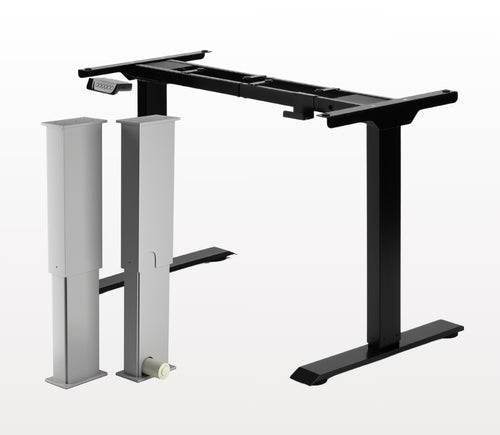
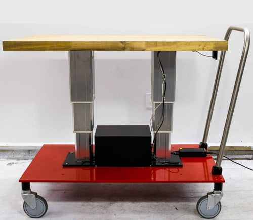
Ja, het L-vormige sta-bureau is flexibel qua oriëntatie en kan naar wens worden geïnstalleerd. Hier is een stapsgewijze handleiding die uitlegt hoe dit mogelijk is: FLT-05 Gebruikershandleiding
OPMERKING: De onderstaande stappen kunnen variëren afhankelijk van het model afstandsbediening dat u heeft. De volgende instructies zijn voor de standaard RT-11-afstandsbediening. Om de maximale hoogte voor uw onderstel in te stellen, ga naar de gewenste hoogte en volg de onderstaande stappen:
- Druk op M; [5 -] verschijnt op het display
- Druk op de UP-knop; [5 -] knippert
- Houd de M-knop ingedrukt totdat u [999] op het display ziet
- De maximale hoogte is nu ingesteld
Om de minimale hoogte voor uw onderstel in te stellen, ga naar de gewenste hoogte en volg de onderstaande stappen:
- Druk op M; [5 -] verschijnt op het display
- Druk op de DOWN-knop; [5 -] knippert
- Houd de M-knop ingedrukt totdat u [000] op het display ziet
- De minimale hoogte is nu ingesteld
Om de limieten te resetten, volgt u de onderstaande stappen:
- Druk op M; [5 -] verschijnt op het display en laat dan los
- Houd M ingedrukt totdat u [555] ziet
- De limieten zijn gereset
OPMERKING: De onderstaande stappen kunnen variëren afhankelijk van het model afstandsbediening dat u heeft. De volgende instructies zijn voor de standaard RT-11-afstandsbediening.
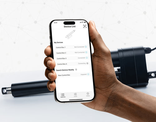
Als u de knoppen van de afstandsbediening ingedrukt moet houden om uw vooraf ingestelde hoogte te bereiken, betekent dit dat uw besturingskast in de momentary-modus staat. Om uw afstandsbediening in de non-momentary-modus te zetten, volgt u de onderstaande stappen
- Zorg ervoor dat er niets onder uw bureau staat, aangezien we de resetprocedure moeten starten
- Houd de DOWN-knop ingedrukt totdat [ASr] op het display verschijnt
- Zodra [ASr] verschijnt, drukt u op [1] en houdt u deze ingedrukt; u kunt twee waarden zien:
a. 10.1 = Non-momentary-modus
b. 10.2 = Momentary-modus
- Voltooi de resetprocedure door de DOWN-knop ingedrukt te houden totdat uw sta-bureau iets zakt en weer omhooggaat.
Onze sta-bureaus hebben 3 instellingen voor botsingsdetectie, die u naar wens kunt instellen. Ga als volgt te werk:
- Zorg ervoor dat er niets onder uw bureau staat, aangezien we de resetprocedure moeten starten
- Houd de DOWN-knop ingedrukt totdat [ASr] op het display verschijnt
- Zodra [ASr] verschijnt, houdt u de UP-[ ^ ]-knop ingedrukt; u kunt drie waarden zien:
a. 10.5 = 11 lbs
b. 10.6 = 22 lbs
c. 10.7 = 33 lbs
- Voltooi de resetprocedure door de DOWN-knop ingedrukt te houden totdat uw sta-bureau iets zakt en weer omhooggaat.
We hebben enkele stappen voor probleemoplossing als u een van de volgende foutcodes ziet op onderstellen met besturingskasten uit de FLTCON-serie:
Controleer de foutcode hier.
Als het probleem na deze stappen aanhoudt, neem dan gerust contact op met onze technische productingenieurs via 1-800-676-6123, of stuur ons een e-mail op sales@progressiveautomations.com.