
Automation Control Systems – Overview & Components
Explore our complete selection of electric linear actuator motion control systems, including control boxes, remotes, rocker switches, joysticks, relays, and advanced controllers. Whether you're looking for wired, wireless, or programmable solutions — this is your central hub to find the right tools for your automation project.


Types of Control Systems
Control boxes offer plug-and-play convenience with built-in safety features and remote compatibility, making them ideal for most applications. They would be paired with remotes that provide flexible wireless or wired operation, from simple up/down functions to programmable presets. For simple operations, rocker switches and joysticks deliver reliable manual operation for straightforward forward/reverse motion control. Our controllers and relays are typically used as additional accessories to enable advanced integration with platforms like Arduino, PLCs, or smart home systems for custom automation. Choosing the right actuator control systems depends on your project’s complexity, level of automation required, and whether you prioritize ease of setup, manual precision, or advanced programmability.
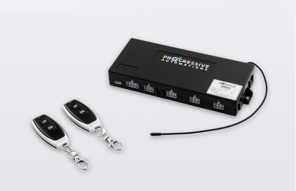
Control Boxes
Our control box range is diverse and designed to suit a variety of applications! From single-channel solutions to multi-channel options of two, three, and four, you have a wide choice for your project. Alongside the range of functions, operational voltage, and feedback compatibility that we offer, our control boxes are also mostly plug-and-play with advanced safety features and synchronous motion control options.
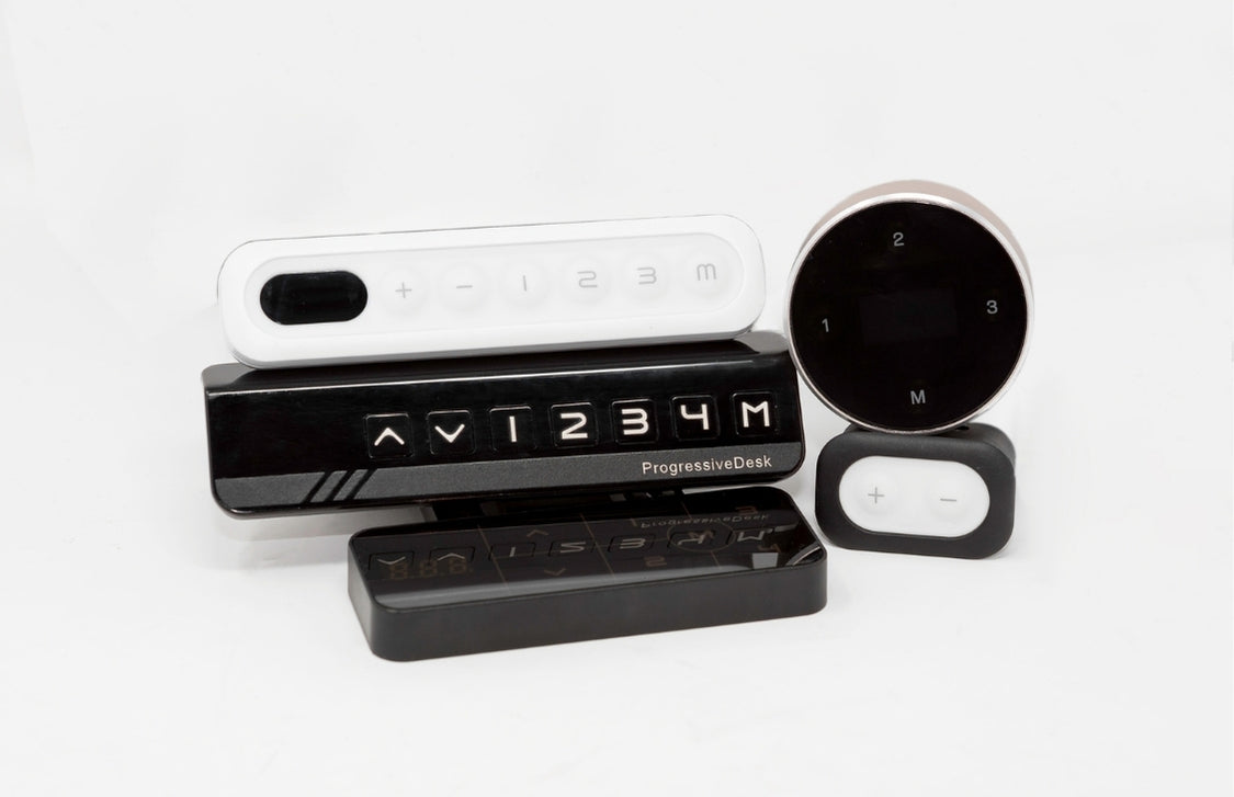
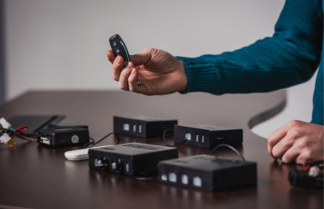
Remotes
Each of our control boxes is operated with remotes, and some of them can be operated with the compatible handheld remote of your choosing. Simply choose the remote(s) that fit your own unique style and function preferences, and/or have backup remotes as a spare. Enjoy all the unique features of our different programmable wired remotes – they can also be used together with our RT-14 wireless remotes for extra convenience!
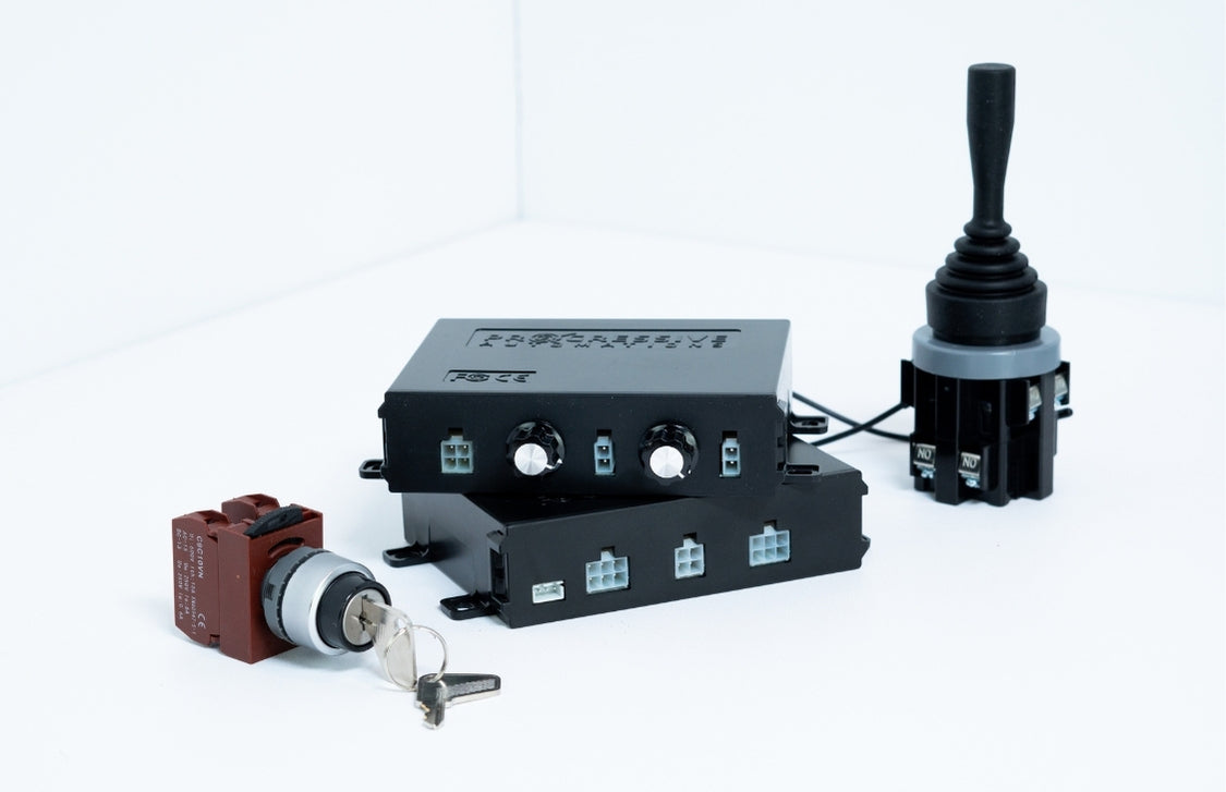
Rocker Switches & Joysticks
Our rocker switches and joysticks provide straightforward manual operation for basic extend/retract motion control. These solutions are perfect for applications where simplicity and reliability are key. Whether you need a single switch for a one-actuator setup or a joystick for more intuitive control, these options give you hands-on operation without requiring additional programming or complex actuator control systems.
Controllers & Relays
For users seeking advanced automation and integration, our controllers and relays for low current controllers to control high current actuators help open the door to custom functionality. These components allow you to fine-tune actuator behavior, integrate with Arduino or PLCs, and expand your actuator control systems with logic-based control and relays.

A control system is the interface that allows you to operate and manage the movement of one or more linear actuators. It typically includes a control box, remote (wired or wireless), and/or joysticks connected to a power supply, giving you the ability to extend, retract, and stop actuators. More advanced actuator control systems add features such as speed control, synchronization, memory presets, or programmable automation.
We offer a wide range of control solutions depending on your application:
- Basic wired controls – Simple extend/retract functions using wired rocker switches, push buttons, remotes, and/or joysticks.
- Wireless controls – RF, Wi-Fi, or Bluetooth solutions for convenient actuator control from a distance.
- Synchronized systems – Keep two or more actuators moving evenly with Hall effect feedback.
- Programmable controllers – Allow custom settings, timer-based functions, and memory presets.
The right choice depends on three main factors:
- Number of actuators – Single or multi-actuator setups require different control boxes.
- Application needs – Decide if you need simple on/off control or advanced functions like synchronization, memory presets, or wireless operation.
- Power supply – Ensure the control box voltage (12V or 24V DC) matches your actuator and that the current rating supports your load.
You can also check the control box compatibility chart to see a summary of our control boxes and determine which model actuators are compatible.
Different control components and relays that are compatible with each other’s feedback requirements, voltage, and current ratings can be mixed and matched. If you are unsure whether something is compatible, reach out to our technical support team for assistance: sales@progressiveautomations.com
Yes. Many of our actuator control systems can be integrated with Arduino, Raspberry Pi, PLCs, and other automation platforms for custom projects. This makes them ideal for both DIY innovators and professional automation projects.