


Sliding bolt latches can be found nearly everywhere we go as a means of locking and securing doors. By integrating DIY electric locks, users can benefit from the added convenience and safety found in home automation. In this article, we will cover how Nathan Bong created his own DIY lock mechanism for an automated sliding bolt latch using the PA-MC1 micro linear actuator. By following this guide, you'll have a DIY automated sliding bolt latch that can enhance the security of your home at the convenient touch of a button. Not only will it add an extra layer of protection to your property, but it will also impress your friends and family with your DIY skills!
Step 1: Gather Materials and Tools Required for DIY Sliding Bolt Latch
The first step is to ensure you have all the necessary tools and components. For this project, we will be using the following components:
1x or 2x Wooden door(s)
1x Sliding bolt latch kit
1x Set of wood screws
1x Spool of wire(s)
1x PA-MC1-4-11-N-12VDC Micro linear actuator
1x BRK-MC1 Mounting brackets set
1x PS-20-12-67 Power supply
1x PA-33 Control box
Optional: 2x CN-W-PCT-212 Reusable Splicing Wire Connectors - 2 Way
Optional: Adhesive buckle cable management ties
Optional: Waterproofing connectors and enclosure box
Nathan chose the PA-MC1-4-11-N-12VDC micro linear actuator because it offers the smallest footprint in our range of actuators for maximum space efficiency at the doorway. The 11 lbs force rating was also more than sufficient to push and pull a door latch while offering a travel speed of 0.75"/sec fully loaded.
The tools used in this project are listed below:
1x Pencil
1x Set square ruler
1x Screwdriver set/kit
1x Wire cutters
1x Wire strippers
Optional: 1x Drill
Step 2: Measuring and Marking For Your Latch

Use a set square ruler to measure the dimensions of your chosen sliding bolt latch kit. Then, use a pencil to mark where you will be drilling holes into the door based on the measurements you have for the sliding bolt latch kit. Check using the set square ruler that your measurements will allow for a horizontally leveled installation. Make the necessary adjustments to match the size of your wooden door(s) before moving to the next step.
Step 3: Making Pilot Holes for Wood Screws

If you have a drill, you may use it to create small pilot holes for your wood screws before installing the sliding bolt latch as drilling makes the process easier. To prepare for the next step, align the wood screws with the pencil markings on the door and then drive the screws into place. You may use a screwdriver and skip using a drill if you have self-tapping type wood screws and your door is softwood, however, hardwood will require pre-drilled holes.
Step 4: Installing the Sliding Bolt Holder

Use a screwdriver to remove the wood screws from the previous step to make room for the sliding bolt holder. Next, align the sliding bolt holder onto the door so that the pre-made holes can be accessed by a screwdriver. Then, use a screwdriver to secure all the wood screws back into position together with the sliding bolt holder. Doing steps 3 and 4 separately helps reduce the risk of potential scratches forming on the sliding bolt holder due to the drill or screwdriver slipping from the user applying too much force when installing without any pre-made holes.
Step 5: Completing the Sliding Bolt Latch Installation

Once the sliding bolt holder is secured, you may insert the sliding bolt to measure and confirm how much of a gap the bolt must travel to lock your door(s). Certain sliding bolt latch kits may allow for some margin room between the open and closed gap position, so be sure to measure the suitable range of travel distance between open and closed. This range of suitable travel distances will usually be compatible with the different stroke length options found in our PA-MC1 micro linear actuator lineup: (0.5 inch, 1 inch, 2 inch, 4 inch, 6 inch, or 8 inch).
Since the 4 inch travel was found suitable in this example, the rest of the components for the sliding bolt latch kit were installed to account for the 4 inch stroke length of the PA-MC1 micro linear actuator. The remaining pieces were installed following a similar process found in steps 3 and 4.

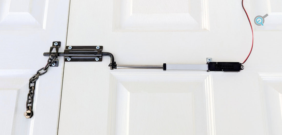
Step 6: Mounting and Attaching the Actuator

Attach the micro linear actuator’s shaft to the sliding bolt and ensure they are securely fastened. This example has a wire passed through the micro linear actuator’s front mounting hole and then secured tightly to the handle of the sliding bolt. The L piece from our BRK-MC1 Mounting brackets set was used to secure the motor housing of the actuator to the door while a wood screw was used to secure the rear mounting hole directly to the door.
Next, apply +12 VDC across the two wire leads of the PA-MC1 micro linear actuator and repeat using -12 VDC for a quick test to make sure the actuator can extend and retract to lock and unlock the door. If everything is working smoothly, proceed to the next step.
Step 7: Wiring The Power Supply and Control Box

Ensure the control box and power supply are securely mounted to the door or placed in a safe location to avoid a tripping hazard. Then, connect the red input wire of the control box with the red output wire of the power supply and connect the black input wire of the control box with the black output wire of the power supply. Extend the length of the wires using the spool of wire(s) you previously prepped according to the size of your door setup. Splice the yellow wire of the control box to the black wire of the actuator and ensure the green wire of the control box is connected to the red wire of the actuator. Our CN-W-PCT-212 Reusable Splicing 2 Way Wire Connectors can be used for indoor installations, however, outdoor applications will require waterproof connectors and could benefit from enclosure boxes. The PS-20-12-67 supply, PA-33 control box, and PA-MC1 actuator all have an ingress protection rating of IP65 or higher for sufficient water resistance if users require their system installed outdoors.
Step 8: Adding Backup Electrical Power and Spare Remotes

In the event of an electrical power outage, a 12 V backup battery or a backup generator for your home similar to Bryan Kelly’s stairwell conversion project can ensure you will always have electrical power to operate. The PA-33 control box comes with 2x wireless remote controls included, allowing options for users to keep the 2nd remote control somewhere safe in case the 1st remote runs out of batteries or goes missing. Each wireless remote control will require 2 x CR2016 3V Lithium cells for operation, so keeping spare batteries can also be beneficial in case a remote control requires battery replacement. After prepping your system with backup power and a spare remote with batteries, your automated sliding bolt latch is complete!
IN SUMMARY
Our IP65 Micro Linear Actuators Model PA-MC1 offers incredible versatility in an ultra-compact package for applications such as DIY electronic locks and latches. High IP65 weather protection also allows for these micro linear actuators to be suitable for door locks in outdoor environments.
We hope you found this as informative and interesting as we did, especially if you were considering micro linear actuator to automate your sliding bolt latch. If you have any queries or wish to discuss our products further, please do not hesitate to contact us! We are experts in what we do and will be happy to assist however we can.
sales@progressiveautomations.com | 1-800-676-6123