


12-24 VDC Contrôleur de moteur CC sans balais - 1 canal - 8A
12-24 VDC Contrôleur de moteur CC sans balais - 1 canal - 8A
Modèle: LC-241
Impossible de charger les disponibilités de retrait


Le contrôleur de moteur CC sans balais LC-241 permet un contrôle à 100 % du cycle de service d’un vérin linéaire CC sans balais. Grâce aux entrées de commande, l’utilisateur dispose d’un contrôle total sur la vitesse et la direction d’un vérin linéaire CC sans balais. Nos vérins linéaires PA-14 et PA-14P peuvent être personnalisés avec un moteur CC sans balais pour fonctionner avec le contrôleur LC-241.
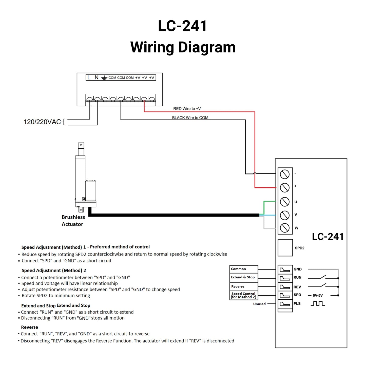
À l’aide des bornes à vis, connectez les vérins linéaires au boîtier de commande. Appliquez 12-24VDC aux fils d’alimentation et suivez les informations d’intégration de commande disponibles dans le manuel de l’utilisateur du LC-241.
Il est important de s’assurer que l’alimentation dispose d’une intensité nominale suffisante pour contrôler les vérins linéaires. Le LC-241 est conçu pour contrôler un vérin linéaire CC sans balais de 12-24VDC tirant au maximum 8A.
* Compatible uniquement avec des moteurs PA-14 et PA-14P sans balais personnalisés (12 ou 24 VDC). Non compatible avec les moteurs standards à balais.
Options personnalisées
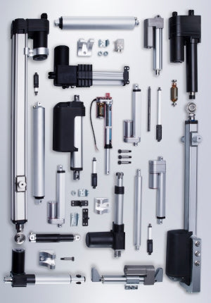
Vous cherchez un actionneur mais les spécifications ne correspondent pas exactement à vos besoins ? Nous disposons d’une vaste liste de possibilités de personnalisation pour vous garantir exactement ce qu’il vous faut pour votre projet. Téléchargez la fiche technique de ce produit et découvrez-en plus sur vos options de personnalisation !
Le contrôleur de moteur CC sans balais LC-241 permet un contrôle à 100 % du cycle de service d’un vérin linéaire CC sans balais. Grâce aux entrées de commande, l’utilisateur dispose d’un contrôle total sur la vitesse et la direction d’un vérin linéaire CC sans balais. Nos vérins linéaires PA-14 et PA-14P peuvent être personnalisés avec un moteur CC sans balais pour fonctionner avec le contrôleur LC-241.
À l’aide des bornes à vis, connectez les vérins linéaires au boîtier de commande. Appliquez 12-24VDC aux fils d’alimentation et suivez les informations d’intégration de commande disponibles dans le manuel de l’utilisateur du LC-241.
Il est important de s’assurer que l’alimentation dispose d’une intensité nominale suffisante pour contrôler les vérins linéaires. Le LC-241 est conçu pour contrôler un vérin linéaire CC sans balais de 12-24VDC tirant au maximum 8A.
* Compatible uniquement avec des moteurs PA-14 et PA-14P sans balais personnalisés (12 ou 24 VDC). Non compatible avec les moteurs standards à balais.
Options personnalisées
Vous cherchez un actionneur mais les spécifications ne correspondent pas exactement à vos besoins ? Nous disposons d’une vaste liste de possibilités de personnalisation pour vous garantir exactement ce qu’il vous faut pour votre projet. Téléchargez la fiche technique de ce produit et découvrez-en plus sur vos options de personnalisation !
Suivre un ensemble de normes est essentiel pour que les entreprises s’assurent que leurs produits et services atteignent un niveau de qualité favorisant la satisfaction client. Chez Progressive Automations, nous visons l’excellence pour nos clients et nous nous efforçons d’apporter des améliorations continues. C’est pourquoi nous sommes ravis d’annoncer que Progressive Automations est désormais certifié ISO 9001:2015 !
Une qualité digne de confiance – En savoir plusFiches techniques
Manuel d'utilisation
Manuel d’utilisation
Comment câbler un vérin linéaire 12 volts
Le vérin linéaire électrique le plus courant utilisé dans l’industrie aujourd’hui est la version 12 Vcc. La fonction d’un vérin linéaire est assez simple : il déplace un objet selon un mouvement linéaire. Selon la façon dont l’unité est câblée, on peut la contrôler de nombreuses manières. Dans cet article, nous aborderons le câblage d’un vérin linéaire 12 volts vers un interrupteur à bascule et un boîtier de commande, ainsi qu’une compréhension de base de comment fonctionne un vérin.

Différence entre moteurs à balais et sans balais
La principale différence est qu’un moteur à balais utilise des balais physiques et un collecteur ...
Étendre et rétracter en continu la course d’un actionneur avec un moteur CC sans balais
Ce tutoriel vous aidera à comprendre les commandes d’un contrôleur de moteur CC sans balais lorsq...