Différentes longueurs de course des modèles sont disponibles sur demande, veuillez nous envoyer un email à : sales@progressiveautomations.com
Ce code d’exemple utilise MegaMoto Plus et un Arduino Uno pour surveiller le courant d’un vérin linéaire; toutefois, des produits similaires peuvent être utilisés en remplacement.
/* Code pour surveiller l’intensité de courant consommée par l’actionneur, et couper l’alimentation si elle
dépasse un certain seuil.
Rédigé par Progressive Automations
19 août 2015
Matériel:
- Cartes de commande RobotPower MegaMoto
- Arduino Uno
- 2 boutons-poussoirs
*/
const int EnablePin = 8;
const int PWMPinA = 11;
const int PWMPinB = 3; // broches pour Megamoto
const int buttonLeft = 4;
const int buttonRight = 5;//boutons pour déplacer le moteur
const int CPin1 = A5; // rétroaction du moteur
int leftlatch = LOW;
int rightlatch = LOW;//verrous du moteur (utilisés pour la logique du code)
int hitLimits = 0;//commencer à 0
int hitLimitsmax = 10;//valeurs pour savoir si les limites de course ont été atteintes
long lastfeedbacktime = 0; // doit être de type long, sinon dépassement
int firstfeedbacktimedelay = 750; //premier délai pour ignorer le pic de courant
int feedbacktimedelay = 50; //délai entre les cycles de rétroaction, fréquence de vérification du moteur
long currentTimefeedback = 0; // doit être de type long, sinon dépassement
int debounceTime = 300; //durée d’anti-rebond des boutons, des valeurs plus faibles rendent les boutons plus sensibles
long lastButtonpress = 0; // minuterie pour l’anti-rebond
long currentTimedebounce = 0;
int CRaw = 0; // valeur d’entrée pour les mesures de courant
int maxAmps = 0; // seuil de déclenchement
bool dontExtend = false;
bool firstRun = true;
bool fullyRetracted = false;//logique du programme
void setup()
{
Serial.begin(9600);
pinMode(EnablePin, OUTPUT);
pinMode(PWMPinA, OUTPUT);
pinMode(PWMPinB, OUTPUT);//Définir les sorties du moteur
pinMode(buttonLeft, INPUT);
pinMode(buttonRight, INPUT);//boutons
digitalWrite(buttonLeft, HIGH);
digitalWrite(buttonRight, HIGH);//activer les pull-up internes
pinMode(CPin1, INPUT);//définir l’entrée de rétroaction
currentTimedebounce = millis();
currentTimefeedback = 0;//Définir les temps initiaux
maxAmps = 15;// DÉFINIR ICI LE COURANT MAXIMUM
}//fin setup
void loop()
{
latchButtons();//vérifier les boutons, voir s’il faut bouger
moveMotor();//vérifier les verrous, faire avancer ou reculer le moteur
}//fin boucle principale
void latchButtons()
{
if (digitalRead(buttonLeft)==LOW)//gauche = avancer
{
currentTimedebounce = millis() - lastButtonpress;// vérifier le temps depuis la dernière pression
if (currentTimedebounce > debounceTime && dontExtend == false)//une fois dontExtend déclenché, ignorer toutes les pressions vers l’avant
{
leftlatch = !leftlatch;// si le moteur est en mouvement, arrêter; s’il est arrêté, démarrer
firstRun = true;// définir l’indicateur firstRun pour ignorer le pic de courant
fullyRetracted = false; // une fois que vous avancez, il n’est plus entièrement rétracté
lastButtonpress = millis();//enregistrer l’heure de la dernière pression sur un bouton
return;
}//fin if
}//fin btnLEFT
if (digitalRead(buttonRight)==LOW)//droite = reculer
{
currentTimedebounce = millis() - lastButtonpress;// vérifier le temps depuis la dernière pression
if (currentTimedebounce > debounceTime)
{
rightlatch = !rightlatch;// si le moteur est en mouvement, arrêter; s’il est arrêté, démarrer
firstRun = true;// définir l’indicateur firstRun pour ignorer le pic de courant
lastButtonpress = millis();//enregistrer l’heure de la dernière pression sur un bouton
return; }//fin if
}//fin btnRIGHT
}//fin latchButtons
void moveMotor()
{
if (leftlatch == HIGH) motorForward(255); //vitesse = 0-255
if (leftlatch == LOW) motorStop();
if (rightlatch == HIGH) motorBack(255); //vitesse = 0-255
if (rightlatch == LOW) motorStop();
}//fin moveMotor
void motorForward(int speeed)
{
while (dontExtend == false && leftlatch == HIGH)
{
digitalWrite(EnablePin, HIGH);
analogWrite(PWMPinA, speeed);
analogWrite(PWMPinB, 0);//déplacer le moteur
if (firstRun == true) delay(firstfeedbacktimedelay); // délai plus long pour ignorer le pic de courant
else delay(feedbacktimedelay); //petit délai pour atteindre la vitesse
getFeedback();
firstRun = false;
latchButtons();//revérifier les boutons
}//fin while
}//fin motorForward
void motorBack (int speeed)
{
while (rightlatch == HIGH)
{
digitalWrite(EnablePin, HIGH);
analogWrite(PWMPinA, 0);
analogWrite(PWMPinB, speeed);//déplacer le moteur
if (firstRun == true) delay(firstfeedbacktimedelay);// délai plus long pour ignorer le pic de courant
else delay(feedbacktimedelay); //petit délai pour atteindre la vitesse
getFeedback();
firstRun = false;
latchButtons();//revérifier les boutons
}//fin while
dontExtend = false;//permettre au moteur de s’étendre à nouveau après rétraction
}//fin motorBack
void motorStop()
{
analogWrite(PWMPinA, 0);
analogWrite(PWMPinB, 0);
digitalWrite(EnablePin, LOW);
firstRun = true;//une fois le moteur arrêté, réactiver firstRun pour tenir compte des pics de courant au démarrage
}//fin stopMotor
void getFeedback()
{
CRaw = analogRead(CPin1); // Lire le courant
if (CRaw == 0 && hitLimits < hitLimitsmax) hitLimits = hitLimits + 1;
else hitLimits = 0; // vérifier si le moteur est aux limites et si le courant s’est arrêté
if (hitLimits == hitLimitsmax && rightlatch == HIGH)
{
rightlatch = LOW; // arrêter le moteur
fullyRetracted = true;
}//fin if
else if (hitLimits == hitLimitsmax && leftlatch == HIGH)
{
leftlatch = LOW;//arrêter le moteur
hitLimits = 0;
}//fin if
if (CRaw > maxAmps)
{
dontExtend = true;
leftlatch = LOW; //arrêter si la rétroaction est supérieure au maximum
}//fin if
lastfeedbacktime = millis();//enregistrer l’heure précédente pour la réception de la rétroaction
}//fin getFeedback
Cet exemple de code montre comment contrôler jusqu’à 4 de nos vérins linéaires avec l’Arduino Uno et le LC-82 MultiMoto Arduino Shield; toutefois, des produits similaires peuvent être utilisés en remplacement. Ce code est uniquement destiné aux modèles d’actionneurs respectant les limites de courant de chaque canal du MultiMoto, tels que les PA-14 et PA-14P.
/* Exemple de code pour piloter jusqu’à 4 actionneurs avec le pilote Robot Power MultiMoto.
Matériel:
- Robot Power MultiMoto
- Arduino Uno
Câblage:
- Connecter les actionneurs aux connexions M1, M2, M3, M4 sur la carte MultiMoto.
- Connecter le négatif (noir) à la borne de droite, le positif (rouge) à celle de gauche.
- Connecter une source 12 volts (minimum 1 A par moteur à vide, 8 A par moteur à pleine charge) aux bornes BAT. Veillez à placer le positif et le négatif aux bons emplacements.
Code modifié par Progressive Automations à partir du code d’exemple fourni par Robot Power
<a href="http://www.robotpower.com/downloads/" rel="nofollow"> http://www.robotpower.com/downloads/</a>
Robot Power MultiMoto v1.0 démo
Ce logiciel est placé dans le domaine public
*/
// inclure la bibliothèque SPI:
#include <SPI.h>
// Broches de sélection esclave L9958 pour SPI
#define SS_M4 14
#define SS_M3 13
#define SS_M2 12
#define SS_M1 11
// Broches de direction L9958
#define DIR_M1 2
#define DIR_M2 3
#define DIR_M3 4
#define DIR_M4 7
// Broches PWM L9958
#define PWM_M1 9
#define PWM_M2 10 // Timer1
#define PWM_M3 5
#define PWM_M4 6 // Timer0
// Activation L9958 pour les 4 moteurs
#define ENABLE_MOTORS 8
int pwm1, pwm2, pwm3, pwm4;
boolean dir1, dir2, dir3, dir4;
void setup() {
unsigned int configWord;
// placez ici votre code d’initialisation, exécuté une seule fois:
pinMode(SS_M1, OUTPUT); digitalWrite(SS_M1, LOW); // HIGH = non sélectionné
pinMode(SS_M2, OUTPUT); digitalWrite(SS_M2, LOW);
pinMode(SS_M3, OUTPUT); digitalWrite(SS_M3, LOW);
pinMode(SS_M4, OUTPUT); digitalWrite(SS_M4, LOW);
// Broches de direction L9958
pinMode(DIR_M1, OUTPUT);
pinMode(DIR_M2, OUTPUT);
pinMode(DIR_M3, OUTPUT);
pinMode(DIR_M4, OUTPUT);
// Broches PWM L9958
pinMode(PWM_M1, OUTPUT); digitalWrite(PWM_M1, LOW);
pinMode(PWM_M2, OUTPUT); digitalWrite(PWM_M2, LOW); // Timer1
pinMode(PWM_M3, OUTPUT); digitalWrite(PWM_M3, LOW);
pinMode(PWM_M4, OUTPUT); digitalWrite(PWM_M4, LOW); // Timer0
// Activation L9958 pour les 4 moteurs
pinMode(ENABLE_MOTORS, OUTPUT);
digitalWrite(ENABLE_MOTORS, HIGH); // HIGH = désactivé
/ /******* Configuration des puces L9958 *********
' Registre de configuration L9958
' Bit
'0 - RES
'1 - DR - réinitialisation
'2 - CL_1 - limite de courant
'3 - CL_2 - limite de courant
'4 - RES
'5 - RES
'6 - RES
'7 - RES
'8 - VSR - vitesse de montée en tension (1 active la limitation, 0 la désactive)
'9 - ISR - vitesse de montée du courant (1 active la limitation, 0 la désactive)
'10 - ISR_DIS - désactivation de la limitation de montée du courant
'11 - OL_ON - activation open‑load (circuit ouvert)
'12 - RES
'13 - RES
'14 - 0 - toujours zéro
'15 - 0 - toujours zéro
*/ // régler sur la limite de courant maximale et désactiver la limitation de montée ISR
configWord = 0b0000010000001100;
SPI.begin();
SPI.setBitOrder(LSBFIRST);
SPI.setDataMode(SPI_MODE1); // polarité d’horloge = bas, phase = haut
// Moteur 1
digitalWrite(SS_M1, LOW);
SPI.transfer(lowByte(configWord));
SPI.transfer(highByte(configWord));
digitalWrite(SS_M1, HIGH);
// Moteur 2
digitalWrite(SS_M2, LOW);
SPI.transfer(lowByte(configWord));
SPI.transfer(highByte(configWord));
digitalWrite(SS_M2, HIGH);
// Moteur 3
digitalWrite(SS_M3, LOW);
SPI.transfer(lowByte(configWord));
SPI.transfer(highByte(configWord));
digitalWrite(SS_M3, HIGH);
// Moteur 4
digitalWrite(SS_M4, LOW);
SPI.transfer(lowByte(configWord));
SPI.transfer(highByte(configWord));
digitalWrite(SS_M4, HIGH);
// Définir les réglages initiaux de l’actionneur pour tirer à vitesse 0 par sécurité
dir1 = 0; dir2 = 0; dir3 = 0; dir4 = 0; // Définir la direction
pwm1 = 0; pwm2 = 0; pwm3 = 0; pwm4 = 0; // Définir la vitesse (0-255)
digitalWrite(ENABLE_MOTORS, LOW);// LOW = activé
} // Fin setup
void loop() {
dir1 = 1;
pwm1 = 255; //définir la direction et la vitesse
digitalWrite(DIR_M1, dir1);
analogWrite(PWM_M1, pwm1); // écrire sur les broches
dir2 = 0;
pwm2 = 128;
digitalWrite(DIR_M2, dir2);
analogWrite(PWM_M2, pwm2);
dir3 = 1;
pwm3 = 255;
digitalWrite(DIR_M3, dir3);
analogWrite(PWM_M3, pwm3);
dir4 = 0;
pwm4 = 128;
digitalWrite(DIR_M4, dir4);
analogWrite(PWM_M4, pwm4);
delay(5000); // attendre une fois que les quatre moteurs sont réglés
dir1 = 0;
pwm1 = 128;
digitalWrite(DIR_M1, dir1);
analogWrite(PWM_M1, pwm1);
dir2 = 1;
pwm2 = 255;
digitalWrite(DIR_M2, dir2);
analogWrite(PWM_M2, pwm2);
dir3 = 0;
pwm3 = 128;
digitalWrite(DIR_M3, dir3);
analogWrite(PWM_M3, pwm3);
dir4 = 1;
pwm4 = 255;
digitalWrite(DIR_M4, dir4);
analogWrite(PWM_M4, pwm4);
delay(5000);
}//fin void loop
Cet exemple de code permet de combiner le contrôleur de vitesse monocanal Wasp avec l’Arduino Uno pour contrôler le mouvement d’un vérin linéaire; toutefois, des produits similaires peuvent être utilisés en remplacement.
/*Exemple de code pour le Robot Power Wasp.
Cet ESC est commandé à l’aide de signaux RC, avec des impulsions
allant de 1000 à 2000 microsecondes.
La boucle principale de ce programme maintient l’actionneur immobile pendant 1 seconde, s’étend pendant 2 secondes,
s’arrête 1 seconde, se rétracte 2 secondes, puis répète.
Modifié par Progressive Automations, à partir de l’exemple d’origine « Sweep » des
bibliothèques d’exemples Arduino.
Matériel:
- 1 contrôleur Wasp
- Arduino Uno
Câblage:
Côté commande:
- Connecter le rouge/noir au +5 V et à la masse (GND)
- Connecter le fil jaune à la broche de signal sur l’Arduino (dans cet exemple, la broche 9)
Côté puissance:
- Connecter le +/- de l’alimentation du moteur aux connexions +/- du Wasp
- Connecter le +/- de l’actionneur aux deux connexions restantes
Cet exemple de code est dans le domaine public.
*/
#include <servo.h>
Servo myservo; // créer un objet servo pour piloter un servo
// sur la plupart des cartes, on peut créer douze objets servo
int pos = 0; // variable pour stocker la position du servo
void setup()
{
myservo.attach(9); // associe le servo sur la broche 9 à l’objet servo
}
void loop()
{
myservo.writeMicroseconds(1500); // signal d’arrêt
delay(1000); //1 seconde
myservo.writeMicroseconds(2000); // signal : pleine vitesse avant
delay(2000); //2 secondes
myservo.writeMicroseconds(1500); // signal d’arrêt
delay(1000); // 1 seconde
myservo.writeMicroseconds(1000); // signal : pleine vitesse arrière
delay(2000); //2 secondes
}
Cet exemple de code utilise nos relais et un Arduino Uno pour commander un vérin linéaire; toutefois, des produits similaires peuvent être utilisés en remplacement. Vous pouvez lire notre article de blog complet pour plus de détails.
const int forwards = 7;
const int backwards = 6;//attribuer la broche INx du relais à une broche de l’Arduino
void setup() {
pinMode(forwards, OUTPUT);//définir le relais comme sortie
pinMode(backwards, OUTPUT);//définir le relais comme sortie
}
void loop() {
digitalWrite(forwards, LOW);
digitalWrite(backwards, HIGH);//Activer le relais dans un sens; les niveaux doivent être différents pour déplacer le moteur
delay(2000); // attendre 2 secondes
digitalWrite(forwards, HIGH);
digitalWrite(backwards, HIGH);//Désactiver les deux relais pour freiner le moteur
delay(2000);// attendre 2 secondes
digitalWrite(forwards, HIGH);
digitalWrite(backwards, LOW);//Activer le relais dans l’autre sens; les niveaux doivent être différents pour déplacer le moteur
delay(2000);// attendre 2 secondes
digitalWrite(forwards, HIGH);
digitalWrite(backwards, HIGH);//Désactiver les deux relais pour freiner le moteur
delay(2000);// attendre 2 secondes
}
Cet exemple de code utilise notre LC-80, un Arduino Uno, n’importe quel vérin linéaire et une source d’alimentation. Des produits similaires peuvent toutefois être utilisés en remplacement. Vous pouvez obtenir plus de détails sur le code et son fonctionnement dans notre article de blog.
//Use the jumpers on the board to select which pins will be used
int EnablePin1 = 13;
int PWMPinA1 = 11;
int PWMPinB1 = 3;
int extendtime = 10 * 1000; // 10 seconds, times 1000 to convert to milliseconds
int retracttime = 10 * 1000; // 10 seconds, times 1000 to convert to milliseconds
int timetorun = 300 * 1000; // 300 seconds, times 1000 to convert to milliseconds
int duty;
int elapsedTime;
boolean keepMoving;
void setup() {
Serial.begin(9600);
pinMode(EnablePin1, OUTPUT);//Enable the board
pinMode(PWMPinA1, OUTPUT);
pinMode(PWMPinB1, OUTPUT);//Set motor outputs
elapsedTime = 0; // Set time to 0
keepMoving = true; //The system will move
}//end setup
void loop() {
if (keepMoving)
{
digitalWrite(EnablePin1, HIGH); // enable the motor
pushActuator();
delay(extendtime);
stopActuator();
delay(10);//small delay before retracting
pullActuator();
delay(retracttime);
stopActuator();
elapsedTime = millis();//how long has it been?
if (elapsedTime > timetorun) {//if it's been 300 seconds, stop
Serial.print("Elapsed time is over max run time. Max run time: ");
Serial.println(timetorun);
keepMoving = false;
}
}//end if
}//end main loop
void stopActuator() {
analogWrite(PWMPinA1, 0);
analogWrite(PWMPinB1, 0); // speed 0-255
}
void pushActuator() {
analogWrite(PWMPinA1, 255);
analogWrite(PWMPinB1, 0); // speed 0-255
}
void pullActuator() {
analogWrite(PWMPinA1, 0);
analogWrite(PWMPinB1, 255);//speed 0-255
}
Ce programme permet d’étendre et de rétracter en continu la course d’un vérin linéaire.
SETUP LOOP CODE
void setup() {
Serial.begin(9600); // initialize serial communication at 9600 bits per second
pinMode(out_lim, INPUT_PULLUP); // configures pin 45 as input pin
pinMode(in_lim, INPUT_PULLUP); // configures pin 53 as input pin
pinMode(run_f, OUTPUT); // configures pin 25 as output pin
pinMode(run_r, OUTPUT); // configures pin 30 as output pin
retract(); // retracts the stroke on startup
delay(500);
}
void extend() // this function enables the motor to run
{
digitalWrite(run_f, LOW);
digitalWrite(run_r, HIGH);
}
void retract() // this function reverses the direction of motor
{
digitalWrite(run_f, LOW);
digitalWrite(run_r, LOW);
}
void run_stop() // this function disables the motor
{
digitalWrite(run_f, HIGH);
digitalWrite(run_r, HIGH);
}
void loop() {
int out_lim_state = digitalRead(out_lim); // reads the limit switches and saves its value
int in_lim_state = digitalRead(in_lim);
Serial.print("outer limit switch value "), Serial.println(out_lim_state); // 0 -> limit switch is pressed
Serial.print("inner limit switch value "), Serial.println(in_lim_state); // 1 -> limit switch is not pressed
if (out_lim_state == 0 && in_lim_state == 1) // if outer limit switch is pressed and inner is not (extended all the way)
{
retract(); // retract the stroke
}
else if (out_lim_state == 1 && in_lim_state == 0) // if inner limit switch is pressed and outer is not (reracted all the way)
{
extend(); // extend the stroke
}
else // otherwise do nothing
{
}
delay(5); // delay in between reads for stability
}
We have data sheets, user manuals, 3D models, wiring diagrams and more in our Resources and Learning Center sections.
Depending on your application, there are different specification requirements you should consider when determining the linear actuator you need. These requirements include force, stroke, speed and mounting dimensions. For detailed actuator information, you can refer to either the datasheet or the specification table located on the selected actuator's product page. You can also contact us to speak with one of our expert engineers.
Duty cycle is the fraction of the working period in which a linear actuator can remain active. You can calculate the duty cycle of a linear actuator by using the following equation: Duty cycle (%) = (Time the linear actuator is active) / (Time for one working period)
For example: With a 25% duty cycle, an actuator can run for 5 minutes continuously before needing to rest for 15 minutes before operating.
Yes, our actuators can be seamless replacements for most applications. Please contact us if you are unsure of which actuator to opt for. You will need to know the voltage rating, force rating, and stroke length needed before we can give a recommendation for a replacement actuator.
Stroke is the travel distance of the extending rod. To find the stroke length you require, measure your application from the fully retracted position to the fully extended position. The difference will equal the stroke length you require.
We always recommend purchasing an actuator with a higher force rating than what the application requires. If unsure of your force requirements, this article may help you calculate this: How to Calculate Force to Find the Right Linear Actuator
Yes. However, it is important to have sufficient voltage and current to be applied to your actuator. Here is an article that may help you further: How to Choose the Right Power Supply for your Linear Actuator
To achieve synchronous motion control, you will require feedback. We offer feedback in the forms of internal limit switches, potentiometers, or hall effect sensors. The following article highlights some Progressive Automations' products that can be used for synchronized control: Controlling Multiple Linear Actuators at the Same Time
There are a number of reasons your linear actuator may be exerting a large amount of noise including over-force, side loading or potential water infiltration. However, it may also be the case that your actuator is simply a high-force rated actuator and therefore has a loud operating noise level. For information on how to possibly overcome this loud noise, please click here. If you are concerned there may be an issue with your actuator, please contact us.
Most of our linear actuators are available for customization. Please refer to your desired product’s datasheet to view the full capabilities of its custom options. Please note there will be a lead time of approximately 20 – 25 business days for production, excluding shipping time. There will also be an additional fee for each actuator that is modified. To find out more about custom orders, please contact us at 1800 – 676 – 6123.
Yes, this is possible. However, it does depend on the units you are currently using. To synchronize actuators, they require a form of feedback such as a potentiometer or hall effect sensors. For more information, see below some of our key content regarding linear actuator synchronization.
Presently, we do not have kits available. However, if you would like a recommendation on the compatibility of certain linear actuators with control systems, please email us at sales@progressiveautomations.com with the following information:
• Required voltage rating
• Required stroke length
• Required force rating
• Dimensional limitations of your application
• Description of your application into which the actuator(s) will be installed
Temperature may be a factor in the functionality of your linear actuator. Please ensure that you use your actuator within the specifications advised in the product datasheet. If you have a specific query related to an actuator and temperature, please contact us.
To do this, please ensure the specifications for your system are compatible with the actuator’s voltage and current ratings. If these specifications align with each other, this may be possible. Please contact us if you are unsure of which actuator to opt for.
To find this information please refer to your product’s data sheet. If your linear actuator was customized, please provide us with images of the product, including your sales order number (if possible) and email this information to sales@progressiveautomations.com
Please click here for a list of 3D CAD models available.
The control box you choose should be able to provide sufficient voltage and current rating to your actuator. If you are unsure of the specifications, please contact us.
Alternatively, you can also find compatible control boxes on your selected linear actuator's product page.
To do this, please ensure the specifications for your system are compatible with the control box’s voltage and current ratings. If these specifications align, this may be possible. if you are unsure of their compatibility, please contact us.
Yes, our PA-35 can control up to four linear actuators using an android/iOS device. For more information, read our detailed article on how to use our Wi-Fi control box and App.
No. However, we have a large variety of control boxes to choose from for each actuator. Alternatively, you may also use rocker switches as a form of motion control.
Yes, however you need to ensure your control box can provide sufficient current draw and compatible voltage. Otherwise, you risk damaging your actuator(s).
As we are primarily manufacturers and distributors, we have a limited amount of sample codes available. While we cannot provide specific coding for your application, we do have a growing list of sample Arduino codes. To access these sample codes, please click here.
We have a range of AC to DC power supplies to choose from in our catalog. As the majority of our actuators are powered via 12 VDC, a 12 VDC automotive battery is also a good solution. Please ensure the connected devices will provide sufficient current to your setup.
You can use your own power supply if it provides sufficient current draw and the right voltage to your system. Otherwise, you run the risk of damaging your actuator(s) and/or control box(es).
Yes, most of our power supplies can be converted up to 230 VAC. To browse our power supply range, click here.
While possible, we recommend using the control box that is included with the lifting column sets. These control boxes are specifically programmed for the lifting columns to work in synchronous motion and using a third-party controller may compromise this.
However, our new LG-11 offers many similar characteristics to the FLT-11 and has the option to be paired with the FLTCON series of control boxes and RT-11 remote for multiple units to travel in synchronous motion. We do have dual lifting column systems available such as FLT-06 or FLT-10 that could provide you with a minimum height of 22 inches from the ground.
All of our lifting columns include control boxes and remotes to control the units. If you would like to know more about the control boxes we use, please contact us.
The only customizable feature for our table/TV lifts is the input voltage. Please note that there will be a lead time of 20 – 25 business days for production of all custom orders.
Our motorized pop-up TV lift is capable of holding up to 60-inch TV’s and our drop-down TV lifts can cater for up to 95-inch TV’s. Click here to browse our TV lifts. For even more information, check out our guide to using TV lifts.
Our table lift weight capacities are dependent on the unit you are choosing. The minimum weight capacity in our line of table lifts is 180 lbs (equal to approximately 80 kg) for our FLT-01 Single Table Lift. The maximum weight capacity in our line of table lifts is 330 lbs (equal to approximately 150 kg) for our FLT-09 Table Lift Set and FLT-05 Table Lift Set.
No, all of our mounting brackets are sold separately to our linear actuators. However, we do produce compatible mounting brackets for each of our linear actuators. To find out which mounting bracket is suitable for your linear actuator, check out your selected actuator's product page (where it will be stated), or browse our mounting bracket catalog.
For this information, please refer to our wiring diagrams.
Please email us photos of your wiring setup so we can look into this further for you. One of our sales engineers will contact you as soon as possible.
Selecting the right electric actuator for your application is a key part of bringing it to life. You need to ensure it meets all your specifications and has the ability to do exactly what you want it to do. That is why we created this handy little flowchart for selecting a linear actuator. It is broken down into four sections, with each section showing different options for our actuators so you can clearly see how they differentiate from each other:
Backdriving is when an actuator starts sliding down under load, when it is either overloaded or when the actuator has been damaged. Watch the video.
What Does Dynamic and Static Load Ratings Mean?Dynamic load rating is the amount of weight an actuator can pull or push safely when being powered. Static load rating is the amount of weight the actuator can hold or withstand without back driving when it is not being powered. For example, let's just say you have an actuator installed on a window and the static load rating of the actuator is 100lbs, it could experience backdriving when there is a high wind event, which means there will be more pressure exerted on the actuator which would exceed the 100lbs load rating of the actuator.
What Is Lateral Loading?Lateral loading is when the actuator experiences forces from the lateral plane. Actuators are not meant to handle lateral forces at all so if it experiences any lateral forces, it will likely damage the actuator or bend the rod. So it's advised never to use lateral forces and always make sure the actuator is fully in line or in sync with your application, so it does not take any load other than the axial load. Watch the video.
Orders can be placed by one of the following ways:
Online: Use our online order process with options to pay by Credit Card or PayPal.
Phone: 1-800 – 676 – 6123
Yes, quantity discounts are applied if you purchase 7 or more of the same product. Quantity discount breakdowns are found on each product page. For more information on our discount structure please contact us.
We accept all major credit cards, PayPal, checks and wire transfers. For customers who wish to set up Net Term accounts, please email us to begin the application process.
For pricing in USD, please ensure you are visiting us from our US site. For pricing in CAD, please ensure you are visiting us from our Canadian site.
All products listed on the website are in stock and available for same-day shipping if your order is placed before 3pm PST. If one of our products is unavailable, we will contact you as soon as possible to inform you when the unit will be available.
Progressive Automations’ shipping fees are calculated based on a variety of factors including but not limited to: location, quantities, and the total weight of your order. Smaller items are shipped via parcel while larger items and bulk orders are shipped via a freight carrier service. We always endeavor to provide competitive shipping prices for all our customers.
Shipping methods are available through online and phone orders. If you wish to receive an estimated shipping cost of your order, this can be done by reviewing your final shopping cart.
We ship via multiple courier companies including FedEx, UPS, DHL and USPS. Your selected courier may vary based on your location. Any large orders are shipped using various freight forwarding companies.
Please contact us if you have any questions about these options or if you would like to ship using a different carrier/your own shipping account.
Canadian and USA customers will not pay or incur any duty taxes on their orders. Customers outside North America may be subject to duty and import fees. Please contact your local government authority for information on import fees and taxes.
Returns or exchanges are accepted within 30 days of receiving your order as long as the product has not been used, modified or damaged. For more information on our return policy please see our Shipping & Returns section.
Delivery to the continental United States may take between 4 to 10 business days. All other deliveries may take approximately 10 to 15 business days depending on your location. Please refer to our shipping policy for more information: Shipping & Returns
Unfortunately, Progressive Automations does not offer free shipping. However, you can get a quantity order discount starting at 7 of the same unit.
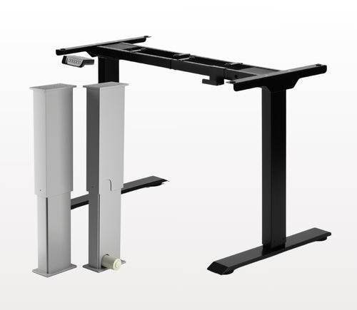
Oui, le bureau assis-debout en L est adaptable à l'orientation et peut être installé selon vos préférences. Voici un article pas à pas qui explique comment procéder : Manuel d'utilisation FLT-05
REMARQUE : Les étapes ci-dessous peuvent varier selon le modèle de télécommande que vous possédez. Les instructions suivantes concernent la télécommande standard RT-11. Pour régler la hauteur maximale de votre cadre, allez à la hauteur souhaitée, puis suivez les étapes ci-dessous :
- Appuyez sur M et vérifiez que [5 -] s'affiche à l'écran
- Appuyez sur la touche HAUT et constatez que [5 -] clignote
- Maintenez la touche M enfoncée jusqu'à voir [999] sur l'écran
- La hauteur maximale est maintenant définie
Pour régler la hauteur minimale de votre cadre, allez à la hauteur souhaitée, puis suivez les étapes ci-dessous :
- Appuyez sur M et vérifiez que [5 -] s'affiche à l'écran
- Appuyez sur la touche BAS et constatez que [5 -] clignote
- Maintenez la touche M enfoncée jusqu'à voir [000] sur l'écran
- La hauteur minimale est maintenant définie
Pour réinitialiser les limites, suivez les étapes ci-dessous :
- Appuyez sur M, vérifiez que [5 -] s'affiche à l'écran, puis relâchez
- Maintenez la touche M enfoncée jusqu'à voir [555]
- Les limites ont été réinitialisées
REMARQUE : Les étapes ci-dessous peuvent varier selon le modèle de télécommande que vous possédez. Les instructions suivantes concernent la télécommande standard RT-11.
Si vous devez maintenir les boutons de la télécommande enfoncés pour atteindre votre hauteur préréglée, cela signifie que votre boîtier de commande est en mode momentané. Pour passer votre télécommande en mode non momentané, suivez les étapes ci-dessous
- Assurez-vous qu'il n'y a rien sous votre bureau, car nous devons lancer la procédure de réinitialisation
- Appuyez et maintenez la touche BAS jusqu'à ce que l'écran affiche [ASr]
- Une fois [ASr] affiché, appuyez et maintenez [1] enfoncé et vous pouvez voir deux valeurs :
a. 10.1 = Mode non momentané
b. 10.2 = Mode momentané
- Terminez la procédure de réinitialisation en maintenant la touche BAS enfoncée jusqu'à ce que votre bureau assis-debout s'abaisse légèrement puis se relève.
Nos bureaux assis-debout disposent de 3 réglages pour la détection des collisions, que vous pouvez ajuster selon vos préférences. Procédez comme suit :
- Assurez-vous qu'il n'y a rien sous votre bureau, car nous devons lancer la procédure de réinitialisation
- Appuyez et maintenez la touche BAS jusqu'à ce que l'écran affiche [ASr]
- Une fois [ASr] affiché, appuyez et maintenez la touche HAUT [ ^ ] et vous pouvez voir trois valeurs :
a. 10.5 = 11 lbs
b. 10.6 = 22 lbs
c. 10.7 = 33 lbs
- Terminez la procédure de réinitialisation en maintenant la touche BAS enfoncée jusqu'à ce que votre bureau assis-debout s'abaisse légèrement puis se relève.
Nous avons préparé quelques étapes de dépannage à suivre si vous voyez l'un des codes d'erreur suivants sur les cadres avec boîtiers de commande de la série FLTCON :
Vérifiez le code d'erreur ici.
Si le problème persiste après avoir suivi ces étapes, n'hésitez pas à contacter nos ingénieurs produits au 1-800-676-6123, ou à nous écrire à sales@progressiveautomations.com.