


We have data sheets, user manuals, 3D models, wiring diagrams and more in our Resources and Learning Center sections.

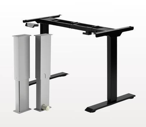
Yes, the L shaped standing desk is orientation-friendly and can be installed by your preference. Here is a step-by-step article that explains how this is possible: FLT-05 User Manual
NOTE: The steps below may vary depending on the remote model that you have. The following instructions were made for the standard RT-11 remote. To set the maximum height for your frame, go to the desired height you would like to set and follow the steps below:
- Press M and see [5 -] indicated on the display
- Press the UP button and notice [5 -] blinks
- Hold the M button until you see [999] on the display
- The maximum height has now been set
To set the minimum height for your frame, go to the desired height you would like to set and follow the steps below:
- Press M and see [5 -] indicated on the display
- Press the DOWN button and notice [5 -] blinks
- Hold the M button until you see [000] on the display
- The minimum height has now been set
To reset the limits, follow the steps below:
- Press M and see [5 -] indicated on the display and release
- Hold the M you see [555]
- Limits have been reset
NOTE: The steps below may vary depending on the remote model you have. The following instructions were made for the standard RT-11 remote.
If you have to hold down the remote’s buttons to get to your pre-set height, this means that your control box is in momentary control. To set your remote to non-momentary mode, follow the steps below
- Make sure that there is nothing underneath your desk, as we have to enter the reset procedure
- Press and hold the DOWN button until the display shows [ASr]
- Once [ASr] is shown, press and hold down [1] and you may see two values:
a. 10.1 = Non-momentary Mode
b. 10.2 = Momentary Mode
- Complete the reset procedure by holding the DOWN button until your standing desk slightly lowers and rises.
Our standing desks have 3 settings for collision detection, and this can be set depending on your preference. To proceed, follow the steps below:
- Make sure that there is nothing underneath your desk as we have to enter the reset procedure
- Press and hold the DOWN button until the display shows [ASr]
- Once [ASr] is shown, press and hold the UP [ ^ ] button and you may see three values:
a. 10.5 = 11 lbs
b. 10.6 = 22 lbs
c. 10.7 = 33 lbs
- Complete the reset procedure by holding the DOWN button until your standing desk slightly lowers and rises.
We have some troubleshooting steps for you to take if you see any of the following error codes on the frames with FLTCON series control boxes:
Сheck the error code here.
If the issue you are experiencing persists after following these steps, please feel free to contact our technical product engineers at 1-800-676-6123, or send us an email at sales@progressiveautomations.com.