


There are two methods of multiple actuator control – parallel and synchronous. Parallel control outputs a constant voltage to each actuator, while synchronous control outputs variable voltage to each actuator.
The process of synchronizing multiple actuators is necessary when implementing two or more actuators to move at the same speed. This can be achieved with two forms of positional feedback – hall effect sensors and multiple turn potentiometers.
Slight variance in actuator production results in a slight variance in actuator speed. This can be corrected by outputting a variable voltage to the actuator to match two actuator speeds. The positional feedback is necessary in order to determine how much voltage is required to output to each actuator.
Synchronization of actuators is important when controlling two or more actuators where precise control is needed. For example, applications that would require multiple actuators to move a load while maintaining equal load distribution across each actuator. If parallel control was used in this type of application, unequal load distribution may occur due to variable stroke speeds and ultimately cause excessive force on one of the actuators.
Hall Effect Sensor
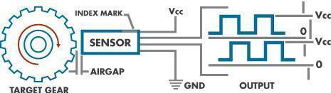
To summarize the Hall Effect theory, Edwin Hall (who discovered the Hall Effect), stated that whenever a magnetic field is applied in a direction perpendicular to the flow of electric current in a conductor, a voltage difference is induced. This voltage can be used to detect whether the sensor is in the proximity of a magnet or not. By attaching a magnet to the shaft of the motor, the sensors can detect when the shaft is parallel to them.
Using a small circuit board, this information can be output as a square wave, which can be counted as a string of pulses. By counting these pulses you can keep track of how many times the motor has spun and how the motor moves.

Some hall effect circuit boards have multiple sensors on them. It is common for them to have 2 sensors at 90 degrees which results in a quadrature output. By counting these pulses and seeing which comes first you can tell the direction that the motor is spinning. Or you can just monitor both sensors and get more counts for more precise control.
Synchronization via Hall Effect sensor feedback can be achieved with Progressive Automations PA-40 Synchronized Dual Hall Effect Actuator Control box.
Potentiometer Synchronization
Multiple turn potentiometers, also known as rheostats or variable resistors, provide an analog representation of an actuator position. The sensor is fixed to a gearing system attached to the motor that turns the potentiometer and therefore adjusts the resistance rating proportionally to the amount of travel that the actuator has made. The total resistance/voltage change can be measured to obtain a full-scale range of the analog value which represents the total stroke distance of the actuator. The potentiometers that are used in Progressive Automations actuators are 10KΩ.
For synchronization purposes, the analog value of each potentiometer is read, which a program/control box can then use to determine the necessary voltage output to each actuator. Potentiometer synchronization can be achieved via microcontroller programming.
Importance of Synchronization
At this point, the methods of synchronization are explained. Now we want to look at why synchronization is important. When the goal of using multiple actuators to push or pull a load is required, we need to ensure that the actuators match speeds precisely. This precision in actuator speed is needed to ensure equal load distribution.Let’s look at an application that requires a pushing force of 700 lbs and two actuators. For this example, we will use two PA-04 IP-66 Linear Actuator with a force rating of 400 lbs each customized with HALL Effect sensors for positional feedback. The combined dynamic force rating of the two actuators, when used in sync, is 800 lbs. The force needed for the system is 700 lbs so the combined actuator force rating of 800 lbs would be acceptable for this application.
Since this application uses two actuators to hold the desired load, the weight must be distributed evenly across the two actuators. In order to ensure even load distribution, the actuators must maintain equal height – if the equal height is not achieved one of the two actuators will bear additional weight and will experience torque (or sideloading). The additional weight and torque may overexert the actuators which result in actuator failure.
Final Control Elements
The importance of synchronizing actuators boils down to ensuring the uniform motion of multiple actuators and preventing actuator failure.
Hall Effect Control Box
When actuators are customized with HALL Effect sensors, the PA-40 control box can be used for hall effect synchronization purposes.
Arduino Microcontroller
Implementation of actuator control can be achieved via Arduino programming. Please visit the following links for more information:
If you have any additional questions, don't hesitate to contact the engineering support an get the instant answer.