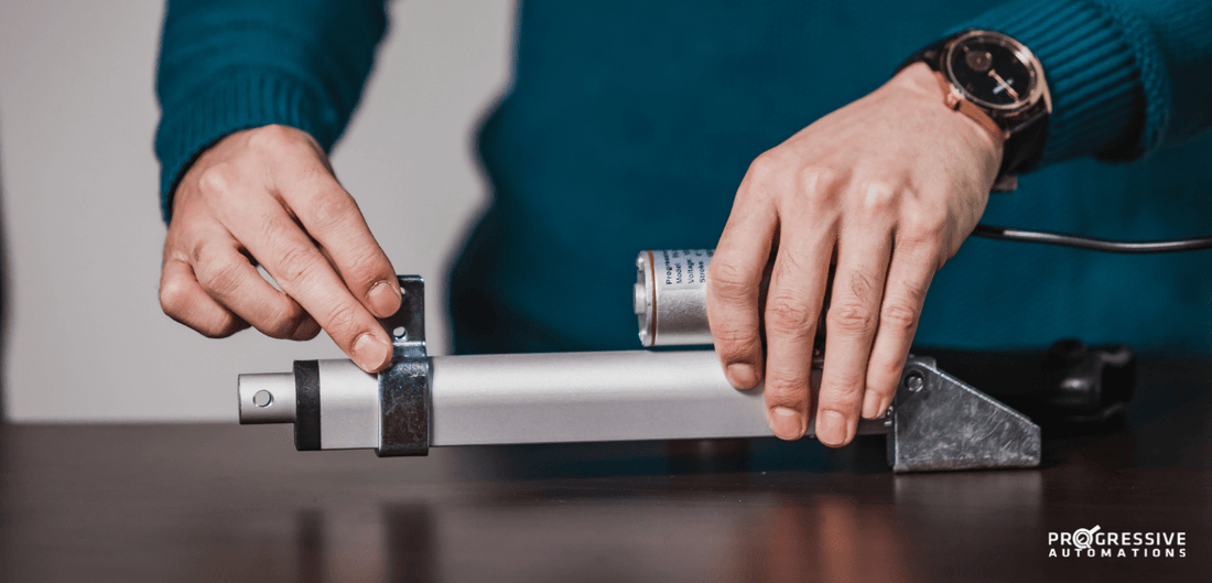
Over time, electronic components will require a repair or replacement as they age. Sometimes it may be due to frequent usage, harsh climates/environments, vibrations, or heavy loads. This would also be the case when it comes to electric linear actuators. Our PA-14 electric actuator repair cost for certain individual components is usually a lot lower than the cost of buying a brand-new actuator. Linear actuator repair practices can also help the environment by reducing overall material wastage. This article will give an idea on how to repair an electric actuator, specifically the steps that can be taken to repair and replace primary components for the PA-14 mini linear actuator. Please note that PA-14 actuators can have slightly different internal layouts depending on their force ratings, which effects gear ratios and if they were custom ordered. Our article is intended as a general guideline on how the repairs can be done as reference. Please note, wearing gloves and safety glasses are recommended when doing repairs and replacements.
In this article, we will cover:
- Replacing the Shaft Enclosure Top
- Replacing Base Covers
- Replacing a DC Motor
- Replacing Metal Motor Gears
- Replacing the Shaft Base with a Limit Switch Arm
Replacing the Shaft Enclosure Top
The shaft enclosure top of the PA-14 can sometimes get chipped, cracked or broken depending on how the actuator was used, and eventually require a replacement. We have outlined below the procedures to replace it with our PRT-14-36:
Step 1
Use a Philips screwdriver to completely remove the Shaft Enclosure Top Cap Screw by turning it counterclockwise. This is the screw located near the top of the actuator’s shaft as seen below.

Step 2
Once the Shaft Enclosure Top Cap Screw is removed, proceed to remove the old Shaft Enclosure Top by pulling it in the direction away from the rest of the actuator’s body. The direction in the red arrow would be seen below.

Step 3
After the old Shaft Enclosure Top is removed completely, place the new Shaft Enclosure Top piece (PRT-14-36) in the same spot the old piece used to be in. The new replacement piece would be pushed in, as seen below.

Step 4
Use a Philips screwdriver to tighten the Shaft Enclosure Top Cap Screw back as it was before, by turning it clockwise.

Replacing Base Covers
A base cover can sometimes get cracked or damaged due to factors like high vibrations, sudden impacts/ collisions, too much load, or exposure to corrosive chemicals. Below are the procedures to replace it with our PRT-14-8. The PRT-14-8b can also be used if a mounting hole rotated 90° is preferred:
Step 1
Completely remove the three base cover screws and washers, seen below in the red circles, by rotating them counterclockwise using a Phillips screwdriver.

Step 2
Remove the old base cover by pulling it in the direction away from the rest of the actuator’s body.
Before:

After:

Step 3
Place the new replacement base cover into place and secure it with the three base cover screws and washers, seen below in the red circles, by rotating them clockwise using a Philips screwdriver.

Replacing a DC Motor
An actuator’s DC Motor can wear out due to overtime frequent usage, or from burning out when electrical power was not turned off. Below are the procedures to replacing a PA-14’s DC motor with our PRT-14-100.
Step 1
Completely remove the three base cover screws and washers, seen below in the red circles, by rotating them counterclockwise using a Philips screwdriver.

Step 2
Remove the Base Cover by pulling it in the direction away from the rest of the actuator’s body.
Before:
After:

Step 3
Remove all the gears that connect from the motor to the shaft in an organized manner, so that the original orientation can be remembered (memorized).

Step 4
Completely remove the three motor base screws, seen below in the red circles, by rotating them counterclockwise using a Philips screwdriver. This is to allow the motor to become loose.

Loose motor:

Step 5
Cut the two wires of the old motor using wire cutters, and then remove the old motor.
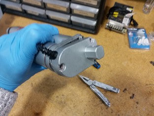
Step 6
Use pliers or a vice to pry off the attached gear on the tip of the old motor as seen in the photo below. A bit of force and grip may be required at this step.

Step 7
Attach the gear that was just removed in Step 6 back onto the new replacement motor PRT-14-100. Pushing the gear into place may require a bit of force and grip when using pliers.
Step 8
Place the new motor’s wires through the wire hole and then solder the two wires of the new replacement motor to the connections on the actuator that was previously connected to the old motor.

Step 9
Tighten the motor back into place as it was before using the three motor base screws below in the red circles by rotating them clockwise using a Philips screwdriver.

Step 10
Place back all the gears that connect from the motor to the shaft in their original orientation. If an excess amount of grease was taken off and lost, adding extra grease is an option. (PA-14 actuators uses the “HP6033-L285 Precision Grease”)

Step 11
Place the base cover back into its original place and secure it with the three base cover screws and washers, seen below in the red circles, by rotating them clockwise using a Philips screwdriver.

Replacing Metal Motor Gears
An actuator’s internal gears can wear out due to overtime wear and tear as well. Below are the procedures to replace it with our PRT-14-7-150. The PRT-14-7-35 are gears used for the PA-14 that have a force rating of 35 lbs.
Step 1
Completely remove the three base cover screws and washers, as seen below in the red circles, by rotating them counterclockwise using a Philips screwdriver.
Step 2
Remove the base cover by pulling it in the direction away from the rest of the actuator’s body.
Before:

After:

Step 3
Remove all the old gears that connect from the motor to the shaft in an organized manner, so that the original orientation can be remembered (memorized).

Step 4
Completely remove the three motor base screws, seen below in the red circles, by rotating them counterclockwise using a Philips screwdriver. This is to allow the motor to be loose.

Loose motor:

Step 5
Use pliers or a vice to pry off the old electric motor gear wheel on the tip of the old motor, as seen in the photo below. A bit of force and grip may be required at this step.

Step 6
Attach the new replacement electric motor gear wheel (if required) to the motor by pushing it into the motor’s tip. Pushing the gear into place may require a bit of force and grip when using pliers.

Step 7
Tighten the motor back into place like it was before using the three motor base screws, seen below in the red circles, by rotating them clockwise using a Philips screwdriver.

Step 8
Place all the gears back that connect from the motor to the shaft in their original orientation. If an excess amount of grease was taken off and lost, adding extra grease is an option. (PA-14 actuators uses the “HP6033-L285 Precision Grease”)

Step 9
Place the base cover back into its original place and secure it with the three base cover screws and washers, seen below in the red circles, by rotating them clockwise using a Philips screwdriver.
Replacing the Shaft Base with a Limit Switch Arm
The shaft base with a limit switch arm is a piece that can have their teeth wear out overtime and decrease the performance of an actuator. Below is the procedure to replace it with our PRT-14-25-50.
Step 1
Use a Philips screwdriver to completely remove the three shaft enclosure base screws (in red circles below) by turning them counterclockwise. These screws are located on the sides of the actuator near the motor at the bottom base.

Step 2
Once the three shaft enclosure base screws are removed, proceed to remove the shaft encloser by pulling it in the direction away from the rest of the actuator’s body. The required direction is seen below.

Step 3
Rotate the actuator’s shaft counterclockwise in the direction of the red arrow below and keep rotating until the shaft comes off for complete removal. Note: let the shaft base with limit switches arm lean against the motor on the side while rotating the shaft. That way the shaft can be removed from the shaft base with limit switches arm.

The result after removing the shaft:

Step 4
Completely remove the three base cover screws and washers, seen below in the red circles, by rotating them counterclockwise using a Philips screwdriver.

Step 5
Remove the base cover by pulling it in the direction away from the rest of the actuator’s body.
Before:

After:

Step 6
Remove all the gears that connect from the motor to the shaft in an organized manner, so that the original orientation can be remembered (memorized).

Step 7
Completely remove the three motor base screws below, seen in the red circles, by rotating them counterclockwise using a Philips screwdriver. This is to allow the motor to be loose.

Step 8
Now that the motor is loose and out of the way, we can rotate the shaft base with limit switches arm freely counterclockwise until it is all the way to the top like in the photo below:

Step 9
Place a metal needle or scribe into the gaps of the shaft drive end support screw, indicated from the orange arrows. Then after that, pry off the shaft drive end support screw by moving it in the direction of the red arrow.

Before removing the shaft drive end support screw:

After removing the shaft drive end support screw:

Step 10
Remove the shaft drive end support by pulling it in the direction away from the rest of the actuator’s body.
Step 11
Remove the old shaft base with the limit switch arm by turning it counterclockwise all the way out.
Step 12
Place in the new replacement shaft base with a limit switch arm (PRT-14-25-50 in this example) by turning it clockwise until it is all the way as far down to the bottom as possible similar to the photo seen below.

Step 13
Place the shaft drive end support back to the original spot.
Step 14
Have the shaft drive end support screw snapped back into place where it was positioned originally. Doing this step may require pliers as seen below.

Step 15
Tighten the motor back into place like it was before using the three motor base screws, seen below in the red circles, by rotating them clockwise using a Philips screwdriver.

Step 16
Place all the gears back that connect from the motor to the shaft in their original orientation. If an excess amount of grease was taken off and lost, adding extra grease is an option. (PA-14 actuators uses the “HP6033-L285 Precision Grease”)

Step 17
Place the base cover back into its original place and secure it with the three base cover screws and washers, seen below in the red circles, by rotating them clockwise.
Step 18
Rotate the actuator’s shaft clockwise in the direction of the red arrow below. Keep rotating until the shaft is back to its original tightness, with the mating replacement shaft base with a limit switch arm.

Step 19
Carefully insert the shaft encloser back to its original place by pushing it in the direction of the red arrow seen below.

Step 20
Use a Philips screwdriver to tighten the three shaft enclosure base screws (in red circles below) back by turning them clockwise using a Philips screwdriver.
The new and improved PA-01 mini actuator (PA-14 upgrade) is the current model we offer with a variety of added benefits. For a comparison, check out the tables below and upgrade with confidence!
|
|
PA-01 |
PA-14 |
|
Dynamic Load Options |
16, 28, 56, 112, 169, 225 lbs |
35, 50, 75, 110, 150 lbs |
|
Highest Load |
225 lbs |
150 lbs |
|
Fastest Speed |
3.54 "/sec |
2.00"/sec |
|
Ingress Protection |
IP65 |
IP54 |
|
Stroke Options |
1" to 40" |
1" to 40" |
|
Hall Effect Feedback |
Optional |
No |
Conclusion
In conclusion, certain repairs are still possible for electric linear actuators that have been damaged or has a decrease in performance. Over the service life of an actuator, they may have to endure frequent usage, harsh climates/environments, vibrations, or heavy loads. Buying a new actuator may be necessary for severe damages, however, our PA-14 actuator’s repair cost for certain components is usually much lower than a new actuator’s price. Repair practices in general can also help the environment by reducing overall material wastage while helping the user gain more hands-on living skills.
In this article, we have shown you how to repair an actuator – our PA-14 in particular. Want to learn about other actuator repair tips? Let us know!