As one of the leading experts on linear motion, we at Progressive Automations design, manufacture, and distribute a wide variety of electric linear actuators for almost any industry, as well as controls and accessories. Some of the common questions we get from individuals entering the industry would be “how does a linear actuator work?” or “what are the internal parts of a linear actuator”. To answer some of these questions, we will be taking a look at the actuator components that are found inside the PA-14 Mini Linear Actuator as it is one of our most popular and readily available units. Having more knowledge on the parts of a linear actuator can also help provide a better understanding on how a linear actuator works. This is beneficial for helping users know how to select, repair, and troubleshoot their actuators in the future.
Major Components

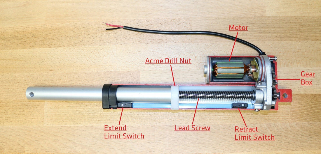
The most readily available version of the PA-14 Mini Linear Actuator is powered by a 12 VDC brushed motor, however, this actuator is also stocked at 24 VDC for certain force and stroke options. The actuator will come with their built-in end of travel limit switches to prevent overextension and retraction, a standard feature for most of our electric linear actuators. Other main actuator components will consist of the gearbox, leadscrew and acme drive nut which also engages the limit switches once it reaches a certain position. The linear actuator diagram above shows the PA-14 in the middle of its stroke travel, meaning it can retract or extend until it reaches the limit switches.
The new and improved PA-01 mini actuator (PA-14 upgrade) is the current model we offer with a variety of added benefits. For a comparison, check out the tables below and upgrade with confidence!
|
|
PA-01 |
PA-14 |
|
Dynamic Load Options |
16, 28, 56, 112, 169, 225 lbs |
35, 50, 75, 110, 150 lbs |
|
Highest Load |
225 lbs |
150 lbs |
|
Fastest Speed |
3.54 "/sec |
2.00"/sec |
|
Ingress Protection |
IP65 |
IP54 |
|
Stroke Options |
1" to 40" |
1" to 40" |
|
Hall Effect Feedback |
Optional |
No |
Power Delivery

By definition, a linear actuator is a device that will move objects in a linear direction. Rotational motion is first generated by the electric motor, often in the thousandths of revolutions per minute. This high-speed rotational motion is then reduced by the gearbox to increase the torque that will then be used to turn the leadscrew. Gearboxes often have a reduction ratio such as “100:1” which means for every 100 rotations of the motor, there will be 1 rotation on the final gear of the gearbox which is connected to the leadscrew.
The leadscrew then turns which results in linear motion of the acme drive nut. This is very similar to driving a screw into a piece of wood. However, instead of the screw moving towards the fixed piece of wood, it is the screw that is fixed and therefore the wood will be moving towards or away from the screw. Leadscrews come with a TPI specification, meaning turns per inch. For example, a TPI of 15 will mean for every 15 turns of the lead-screw, the connecting drive nut will move an inch.
The motor speed, gear reduction, and lead-screw TPI determine the final speed of the linear actuator. Our actuators have various force options per model. Those models typically have the same motor but the gear reduction and TPI changes. The rule of thumb is by reducing the speed, the force increases, and vice versa.
Stroke Travel
One of the most convenient additions to a linear actuator is the built-in end of travel limit switches. Essentially this prevents the actuator from reaching the physical movement limits of the housing which will likely cause the motor to burn out. It also allows for a smoother stopping motion once the end of travel is reached.
The system employed for these limit switches is very simple and robust. The electricity from your power supply essentially goes from the input connector of the actuator to the motor, to the limit switches before it completes the circuit back to the connector as shown in the linear actuator diagram below.

The limit switches break the path of travel of the electricity once it is touched by the drive nut. Now because of the unidirectional diode on each limit switch, electricity is only allowed to flow through in one direction. For example, the direction of electricity required to extend the actuator will be stopped by the extended limit switch and its diode as seen below.

Diode preventing current flow to protect actuator from overextension
However, the diode will allow the opposite direction of electricity which will be required to retract the actuator. Once the drive screw has retracted and is no longer touching the extended limit switch, then the electricity goes through the limit switch again allowing movement in both directions.

Diode allowing current flow for retracting
Conclusion
In conclusion, electric linear actuators can be used for many applications that require linear motion. Having more knowledge on the internal parts of a linear actuator and how the actuator components work can allow users to have a better understanding on how to select and troubleshoot their actuators in the future. For more information on the components of electric linear actuators, please feel free to contact us at 1-800-676-6123 by phone or email us at sales@progressiveautomations.com. We are happy to help you with any questions you may have!