Different stroke lengths of models are available upon request, please email us at: sales@progressiveautomations.com
Tento ukážkový kód používa MegaMoto Plus a Arduino Uno na sledovanie prúdu lineárneho aktuátora; podobné produkty však možno použiť ako náhrady.
/* Code to monitor the current amp draw of the actuator, and to cut power if it
rises above a certain amount.
Written by Progressive Automations
August 19th, 2015
Hardware:
- RobotPower MegaMoto control boards
- Arduino Uno
- 2 pushbuttons
*/
const int EnablePin = 8;
const int PWMPinA = 11;
const int PWMPinB = 3; // piny pre Megamoto
const int buttonLeft = 4;
const int buttonRight = 5;//tlačidlá na pohyb motora
const int CPin1 = A5; // spätná väzba motora
int leftlatch = LOW;
int rightlatch = LOW;//zámky motora (použité v logike kódu)
int hitLimits = 0;//začnite na 0
int hitLimitsmax = 10;//hodnoty na zistenie, či boli dosiahnuté koncové dorazy
long lastfeedbacktime = 0; // musí byť typu long, inak dôjde k pretečeniu
int firstfeedbacktimedelay = 750; // prvé oneskorenie na ignorovanie prúdovej špičky
int feedbacktimedelay = 50; // oneskorenie medzi cyklami spätnej väzby; ako často sa má kontrolovať motor
long currentTimefeedback = 0; // musí byť typu long, inak dôjde k pretečeniu
int debounceTime = 300; // čas na odrušenie zákmitov tlačidiel; nižšie hodnoty zvyšujú citlivosť
long lastButtonpress = 0; // časovač na odrušenie zákmitov
long currentTimedebounce = 0;
int CRaw = 0; // vstupná hodnota pre meranie prúdu
int maxAmps = 0; // spúšťacia hranica
bool dontExtend = false;
bool firstRun = true;
bool fullyRetracted = false;//logika programu
void setup()
{
Serial.begin(9600);
pinMode(EnablePin, OUTPUT);
pinMode(PWMPinA, OUTPUT);
pinMode(PWMPinB, OUTPUT);//Nastavenie výstupov motora
pinMode(buttonLeft, INPUT);
pinMode(buttonRight, INPUT);//tlačidlá
digitalWrite(buttonLeft, HIGH);
digitalWrite(buttonRight, HIGH);//povoliť vnútorné pull‑up odpory
pinMode(CPin1, INPUT);//nastaviť vstup spätnej väzby
currentTimedebounce = millis();
currentTimefeedback = 0;//nastaviť počiatočné časy
maxAmps = 15;// NASTAVTE MAXIMÁLNY PRÚD TU
}//end setup
void loop()
{
latchButtons();//skontroluje tlačidlá, či sa treba pohnúť
moveMotor();//skontroluje zámky, vysunie alebo zasunie motor
}//end main loop
void latchButtons()
{
if (digitalRead(buttonLeft)==LOW)//ľavé je dopredu
{
currentTimedebounce = millis() - lastButtonpress;// skontroluje čas od posledného stlačenia
if (currentTimedebounce > debounceTime && dontExtend == false)//keď je nastavené dontExtend, ignorujú sa všetky stlačenia dopredu
{
leftlatch = !leftlatch;// ak sa motor hýbe, zastav; ak stojí, začni sa hýbať
firstRun = true;// nastaví príznak firstRun na ignorovanie prúdovej špičky
fullyRetracted = false; // po pohybe dopredu už nie je úplne zasunutý
lastButtonpress = millis();//uloží čas posledného stlačenia tlačidla
return;
}//end if
}//end btnLEFT
if (digitalRead(buttonRight)==LOW)//pravé je dozadu
{
currentTimedebounce = millis() - lastButtonpress;// skontroluje čas od posledného stlačenia
if (currentTimedebounce > debounceTime)
{
rightlatch = !rightlatch;// ak sa motor hýbe, zastav; ak stojí, začni sa hýbať
firstRun = true;// nastaví príznak firstRun na ignorovanie prúdovej špičky
lastButtonpress = millis();//uloží čas posledného stlačenia tlačidla
return; }//end if
}//end btnRIGHT
}//end latchButtons
void moveMotor()
{
if (leftlatch == HIGH) motorForward(255); //rýchlosť = 0-255
if (leftlatch == LOW) motorStop();
if (rightlatch == HIGH) motorBack(255); //rýchlosť = 0-255
if (rightlatch == LOW) motorStop();
}//end moveMotor
void motorForward(int speeed)
{
while (dontExtend == false && leftlatch == HIGH)
{
digitalWrite(EnablePin, HIGH);
analogWrite(PWMPinA, speeed);
analogWrite(PWMPinB, 0);//pohnúť motorom
if (firstRun == true) delay(firstfeedbacktimedelay); // väčšie oneskorenie na ignorovanie prúdovej špičky
else delay(feedbacktimedelay); //malé oneskorenie na dosiahnutie rýchlosti
getFeedback();
firstRun = false;
latchButtons();//znova skontrolovať tlačidlá
}//end while
}//end motorForward
void motorBack (int speeed)
{
while (rightlatch == HIGH)
{
digitalWrite(EnablePin, HIGH);
analogWrite(PWMPinA, 0);
analogWrite(PWMPinB, speeed);//pohnúť motorom
if (firstRun == true) delay(firstfeedbacktimedelay);// väčšie oneskorenie na ignorovanie prúdovej špičky
else delay(feedbacktimedelay); //malé oneskorenie na dosiahnutie rýchlosti
getFeedback();
firstRun = false;
latchButtons();//znova skontrolovať tlačidlá
}//end while
dontExtend = false;//po zasunutí opäť umožní vysúvanie motora
}//end motorBack
void motorStop()
{
analogWrite(PWMPinA, 0);
analogWrite(PWMPinB, 0);
digitalWrite(EnablePin, LOW);
firstRun = true;//po zastavení motora znova povolí firstRun kvôli nábehovým prúdovým špičkám
}//end stopMotor
void getFeedback()
{
CRaw = analogRead(CPin1); // Čítať prúd
if (CRaw == 0 && hitLimits < hitLimitsmax) hitLimits = hitLimits + 1;
else hitLimits = 0; // skontrolovať, či je motor na dorazoch a prúd sa zastavil
if (hitLimits == hitLimitsmax && rightlatch == HIGH)
{
rightlatch = LOW; // zastaviť motor
fullyRetracted = true;
}//end if
else if (hitLimits == hitLimitsmax && leftlatch == HIGH)
{
leftlatch = LOW;//zastaviť motor
hitLimits = 0;
}//end if
if (CRaw > maxAmps)
{
dontExtend = true;
leftlatch = LOW; //zastaviť, ak je prúd nad maximom
}//end if
lastfeedbacktime = millis();//uložiť predchádzajúci čas prijatia spätnej väzby
}//end getFeedback
Tento ukážkový kód ukazuje, ako ovládať až 4 naše lineárne aktuátory pomocou Arduino Uno a LC-82 MultiMoto Arduino Shield; podobné produkty však možno použiť ako náhrady. Tento kód je určený iba pre modely aktuátorov v rámci prúdových obmedzení na každom kanáli MultiMoto, ako sú PA-14 a PA-14P.
/* Example code to control up to 4 actuators, using the Robot Power MultiMoto driver.
Hardware:
- Robot Power MultiMoto
- Arduino Uno
Wiring:
- Connect actuators to the M1, M2, M3, M4 connections on the MultiMoto board.
- Connect the negative (black) to the right connection, positive (red) to the left.
- Connect a 12 volt source (minimum 1A per motor if unloaded, 8A per motor if fully loaded)to the BAT terminals. Ensure that positive and negative are placed in the correct spots.
Code modified by Progressive Automations from the example code provided by Robot Power
<a href="http://www.robotpower.com/downloads/" rel="nofollow"> http://www.robotpower.com/downloads/</a>
Robot Power MultiMoto v1.0 demo
This software is released into the Public Domain
*/
// include the SPI library:
#include <SPI.h>
// L9958 slave select pins for SPI
#define SS_M4 14
#define SS_M3 13
#define SS_M2 12
#define SS_M1 11
// L9958 DIRection pins
#define DIR_M1 2
#define DIR_M2 3
#define DIR_M3 4
#define DIR_M4 7
// L9958 PWM pins
#define PWM_M1 9
#define PWM_M2 10 // Timer1
#define PWM_M3 5
#define PWM_M4 6 // Timer0
// L9958 Enable for all 4 motors
#define ENABLE_MOTORS 8
int pwm1, pwm2, pwm3, pwm4;
boolean dir1, dir2, dir3, dir4;
void setup() {
unsigned int configWord;
// put your setup code here, to run once:
pinMode(SS_M1, OUTPUT); digitalWrite(SS_M1, LOW); // HIGH = nevybraný
pinMode(SS_M2, OUTPUT); digitalWrite(SS_M2, LOW);
pinMode(SS_M3, OUTPUT); digitalWrite(SS_M3, LOW);
pinMode(SS_M4, OUTPUT); digitalWrite(SS_M4, LOW);
// L9958 smerové piny
pinMode(DIR_M1, OUTPUT);
pinMode(DIR_M2, OUTPUT);
pinMode(DIR_M3, OUTPUT);
pinMode(DIR_M4, OUTPUT);
// L9958 PWM piny
pinMode(PWM_M1, OUTPUT); digitalWrite(PWM_M1, LOW);
pinMode(PWM_M2, OUTPUT); digitalWrite(PWM_M2, LOW); // Timer1
pinMode(PWM_M3, OUTPUT); digitalWrite(PWM_M3, LOW);
pinMode(PWM_M4, OUTPUT); digitalWrite(PWM_M4, LOW); // Timer0
// L9958 povolenie pre všetky 4 motory
pinMode(ENABLE_MOTORS, OUTPUT);
digitalWrite(ENABLE_MOTORS, HIGH); // HIGH = zakázané
/ /******* Nastaviť čipy L9958 *********
' Konfiguračný register L9958
' Bit
'0 - RES
'1 - DR - reset
'2 - CL_1 - obmedzenie prúdu
'3 - CL_2 - obmedzenie prúdu
'4 - RES
'5 - RES
'6 - RES
'7 - RES
'8 - VSR - rýchlosť nárastu napätia (1 zapne obmedzenie nárastu, 0 vypne)
'9 - ISR - rýchlosť nárastu prúdu (1 zapne obmedzenie nárastu, 0 vypne)
'10 - ISR_DIS - vypnutie obmedzenia nárastu prúdu
'11 - OL_ON - povoliť otvorenú záťaž
'12 - RES
'13 - RES
'14 - 0 - vždy nula
'15 - 0 - vždy nula
*/ // nastaviť na maximálne obmedzenie prúdu a vypnúť obmedzenie nárastu ISR
configWord = 0b0000010000001100;
SPI.begin();
SPI.setBitOrder(LSBFIRST);
SPI.setDataMode(SPI_MODE1); // clock pol = low, phase = high
// Motor 1
digitalWrite(SS_M1, LOW);
SPI.transfer(lowByte(configWord));
SPI.transfer(highByte(configWord));
digitalWrite(SS_M1, HIGH);
// Motor 2
digitalWrite(SS_M2, LOW);
SPI.transfer(lowByte(configWord));
SPI.transfer(highByte(configWord));
digitalWrite(SS_M2, HIGH);
// Motor 3
digitalWrite(SS_M3, LOW);
SPI.transfer(lowByte(configWord));
SPI.transfer(highByte(configWord));
digitalWrite(SS_M3, HIGH);
// Motor 4
digitalWrite(SS_M4, LOW);
SPI.transfer(lowByte(configWord));
SPI.transfer(highByte(configWord));
digitalWrite(SS_M4, HIGH);
//Nastaviť počiatočné nastavenia aktuátorov na zasúvanie pri rýchlosti 0 ako bezpečnostné opatrenie
dir1 = 0; dir2 = 0; dir3 = 0; dir4 = 0; // Nastaviť smer
pwm1 = 0; pwm2 = 0; pwm3 = 0; pwm4 = 0; // Nastaviť rýchlosť (0-255)
digitalWrite(ENABLE_MOTORS, LOW);// LOW = povolené
} // End setup
void loop() {
dir1 = 1;
pwm1 = 255; //nastaviť smer a rýchlosť
digitalWrite(DIR_M1, dir1);
analogWrite(PWM_M1, pwm1); // zápis na piny
dir2 = 0;
pwm2 = 128;
digitalWrite(DIR_M2, dir2);
analogWrite(PWM_M2, pwm2);
dir3 = 1;
pwm3 = 255;
digitalWrite(DIR_M3, dir3);
analogWrite(PWM_M3, pwm3);
dir4 = 0;
pwm4 = 128;
digitalWrite(DIR_M4, dir4);
analogWrite(PWM_M4, pwm4);
delay(5000); // počkať po nastavení všetkých štyroch motorov
dir1 = 0;
pwm1 = 128;
digitalWrite(DIR_M1, dir1);
analogWrite(PWM_M1, pwm1);
dir2 = 1;
pwm2 = 255;
digitalWrite(DIR_M2, dir2);
analogWrite(PWM_M2, pwm2);
dir3 = 0;
pwm3 = 128;
digitalWrite(DIR_M3, dir3);
analogWrite(PWM_M3, pwm3);
dir4 = 1;
pwm4 = 255;
digitalWrite(DIR_M4, dir4);
analogWrite(PWM_M4, pwm4);
delay(5000);
}//koniec void loop
Tento ukážkový kód je určený na kombináciu jednokanálového regulátora rýchlosti Wasp s Arduinom Uno na riadenie pohybu lineárneho aktuátora; podobné produkty však možno použiť ako náhrady.
/*Sample code for the Robot Power Wasp.
This ESC is controlled using RC signals, with pulses
ranging from 1000 - 2000 microseconds.
The main loop of this program holds the actuator still for 1 second, extends for 2 seconds,
stops for 1 second, retracts for 2 seconds, and repeats.
Modified by Progressive Automations, using the original example code "Sweep" from the
Arduino example libraries.
Hardware:
- 1 Wasp Controller
- Arduino Uno
Wiring:
Control side:
- Connect the red/black to +5v and GND
- Connect the yellow wire to your signal pin on the Arduino (in this example, pin 9)
Power Side:
- Connect the +/- of the motors power supply to the +/- connections on the Wasp
- Connect the +/- of the actuator to the remaining two connections
This example code is in the public domain.
*/
#include <servo.h>
Servo myservo; // vytvorí objekt servo na ovládanie serva
// na väčšine dosiek možno vytvoriť dvanásť objektov servo
int pos = 0; // premenná na uloženie polohy serva
void setup()
{
myservo.attach(9); // pripojí servo na pine 9 k objektu servo
}
void loop()
{
myservo.writeMicroseconds(1500); // stop signál
delay(1000); //1 sekunda
myservo.writeMicroseconds(2000); // signál: plná rýchlosť dopredu
delay(2000); //2 sekundy
myservo.writeMicroseconds(1500); // stop signál
delay(1000); // 1 sekunda
myservo.writeMicroseconds(1000); // signál: plná rýchlosť dozadu
delay(2000); //2 sekundy
}
Tento ukážkový kód využíva naše relé a Arduino Uno na ovládanie lineárneho aktuátora; podobné produkty však možno použiť ako náhrady. Viac podrobností nájdete v našom úplnom blogovom príspevku.
const int forwards = 7;
const int backwards = 6;//priraďte pin INx relé k pinu Arduina
void setup() {
pinMode(forwards, OUTPUT);//nastaviť relé ako výstup
pinMode(backwards, OUTPUT);//nastaviť relé ako výstup
}
void loop() {
digitalWrite(forwards, LOW);
digitalWrite(backwards, HIGH);//Aktivujte relé v jednom smere; úrovne musia byť odlišné, aby sa motor pohol
delay(2000); // počkať 2 sekundy
digitalWrite(forwards, HIGH);
digitalWrite(backwards, HIGH);//Deaktivujte obe relé, aby sa motor zabrzdil
delay(2000);// počkať 2 sekundy
digitalWrite(forwards, HIGH);
digitalWrite(backwards, LOW);//Aktivujte relé v opačnom smere; úrovne musia byť odlišné, aby sa motor pohol
delay(2000);// počkať 2 sekundy
digitalWrite(forwards, HIGH);
digitalWrite(backwards, HIGH);//Deaktivujte obe relé, aby sa motor zabrzdil
delay(2000);// počkať 2 sekundy
}
Tento ukážkový kód používa náš LC-80, Arduino Uno, ľubovoľný lineárny aktuátor a zdroj napájania; podobné produkty však možno použiť ako náhradu. Viac podrobností o kóde a o tom, čo robí, nájdete v našom blogovom príspevku.
//Use the jumpers on the board to select which pins will be used
int EnablePin1 = 13;
int PWMPinA1 = 11;
int PWMPinB1 = 3;
int extendtime = 10 * 1000; // 10 seconds, times 1000 to convert to milliseconds
int retracttime = 10 * 1000; // 10 seconds, times 1000 to convert to milliseconds
int timetorun = 300 * 1000; // 300 seconds, times 1000 to convert to milliseconds
int duty;
int elapsedTime;
boolean keepMoving;
void setup() {
Serial.begin(9600);
pinMode(EnablePin1, OUTPUT);//Enable the board
pinMode(PWMPinA1, OUTPUT);
pinMode(PWMPinB1, OUTPUT);//Set motor outputs
elapsedTime = 0; // Set time to 0
keepMoving = true; //The system will move
}//end setup
void loop() {
if (keepMoving)
{
digitalWrite(EnablePin1, HIGH); // enable the motor
pushActuator();
delay(extendtime);
stopActuator();
delay(10);//small delay before retracting
pullActuator();
delay(retracttime);
stopActuator();
elapsedTime = millis();//how long has it been?
if (elapsedTime > timetorun) {//if it's been 300 seconds, stop
Serial.print("Elapsed time is over max run time. Max run time: ");
Serial.println(timetorun);
keepMoving = false;
}
}//end if
}//end main loop
void stopActuator() {
analogWrite(PWMPinA1, 0);
analogWrite(PWMPinB1, 0); // speed 0-255
}
void pushActuator() {
analogWrite(PWMPinA1, 255);
analogWrite(PWMPinB1, 0); // speed 0-255
}
void pullActuator() {
analogWrite(PWMPinA1, 0);
analogWrite(PWMPinB1, 255);//speed 0-255
}
Tento program možno použiť na nepretržité vysúvanie a zasúvanie zdvihu lineárneho aktuátora.
SETUP LOOP CODE
void setup() {
Serial.begin(9600); // initialize serial communication at 9600 bits per second
pinMode(out_lim, INPUT_PULLUP); // configures pin 45 as input pin
pinMode(in_lim, INPUT_PULLUP); // configures pin 53 as input pin
pinMode(run_f, OUTPUT); // configures pin 25 as output pin
pinMode(run_r, OUTPUT); // configures pin 30 as output pin
retract(); // retracts the stroke on startup
delay(500);
}
void extend() // this function enables the motor to run
{
digitalWrite(run_f, LOW);
digitalWrite(run_r, HIGH);
}
void retract() // this function reverses the direction of motor
{
digitalWrite(run_f, LOW);
digitalWrite(run_r, LOW);
}
void run_stop() // this function disables the motor
{
digitalWrite(run_f, HIGH);
digitalWrite(run_r, HIGH);
}
void loop() {
int out_lim_state = digitalRead(out_lim); // reads the limit switches and saves its value
int in_lim_state = digitalRead(in_lim);
Serial.print("outer limit switch value "), Serial.println(out_lim_state); // 0 -> limit switch is pressed
Serial.print("inner limit switch value "), Serial.println(in_lim_state); // 1 -> limit switch is not pressed
if (out_lim_state == 0 && in_lim_state == 1) // if outer limit switch is pressed and inner is not (extended all the way)
{
retract(); // retract the stroke
}
else if (out_lim_state == 1 && in_lim_state == 0) // if inner limit switch is pressed and outer is not (reracted all the way)
{
extend(); // extend the stroke
}
else // otherwise do nothing
{
}
delay(5); // delay in between reads for stability
}
We have data sheets, user manuals, 3D models, wiring diagrams and more in our Resources and Learning Center sections.
Depending on your application, there are different specification requirements you should consider when determining the linear actuator you need. These requirements include force, stroke, speed and mounting dimensions. For detailed actuator information, you can refer to either the datasheet or the specification table located on the selected actuator's product page. You can also contact us to speak with one of our expert engineers.
Duty cycle is the fraction of the working period in which a linear actuator can remain active. You can calculate the duty cycle of a linear actuator by using the following equation: Duty cycle (%) = (Time the linear actuator is active) / (Time for one working period)
For example: With a 25% duty cycle, an actuator can run for 5 minutes continuously before needing to rest for 15 minutes before operating.
Yes, our actuators can be seamless replacements for most applications. Please contact us if you are unsure of which actuator to opt for. You will need to know the voltage rating, force rating, and stroke length needed before we can give a recommendation for a replacement actuator.
Stroke is the travel distance of the extending rod. To find the stroke length you require, measure your application from the fully retracted position to the fully extended position. The difference will equal the stroke length you require.
We always recommend purchasing an actuator with a higher force rating than what the application requires. If unsure of your force requirements, this article may help you calculate this: How to Calculate Force to Find the Right Linear Actuator
Yes. However, it is important to have sufficient voltage and current to be applied to your actuator. Here is an article that may help you further: How to Choose the Right Power Supply for your Linear Actuator
To achieve synchronous motion control, you will require feedback. We offer feedback in the forms of internal limit switches, potentiometers, or hall effect sensors. The following article highlights some Progressive Automations' products that can be used for synchronized control: Controlling Multiple Linear Actuators at the Same Time
There are a number of reasons your linear actuator may be exerting a large amount of noise including over-force, side loading or potential water infiltration. However, it may also be the case that your actuator is simply a high-force rated actuator and therefore has a loud operating noise level. For information on how to possibly overcome this loud noise, please click here. If you are concerned there may be an issue with your actuator, please contact us.
Most of our linear actuators are available for customization. Please refer to your desired product’s datasheet to view the full capabilities of its custom options. Please note there will be a lead time of approximately 20 – 25 business days for production, excluding shipping time. There will also be an additional fee for each actuator that is modified. To find out more about custom orders, please contact us at 1800 – 676 – 6123.
Yes, this is possible. However, it does depend on the units you are currently using. To synchronize actuators, they require a form of feedback such as a potentiometer or hall effect sensors. For more information, see below some of our key content regarding linear actuator synchronization.
Presently, we do not have kits available. However, if you would like a recommendation on the compatibility of certain linear actuators with control systems, please email us at sales@progressiveautomations.com with the following information:
• Required voltage rating
• Required stroke length
• Required force rating
• Dimensional limitations of your application
• Description of your application into which the actuator(s) will be installed
Temperature may be a factor in the functionality of your linear actuator. Please ensure that you use your actuator within the specifications advised in the product datasheet. If you have a specific query related to an actuator and temperature, please contact us.
To do this, please ensure the specifications for your system are compatible with the actuator’s voltage and current ratings. If these specifications align with each other, this may be possible. Please contact us if you are unsure of which actuator to opt for.
To find this information please refer to your product’s data sheet. If your linear actuator was customized, please provide us with images of the product, including your sales order number (if possible) and email this information to sales@progressiveautomations.com
Please click here for a list of 3D CAD models available.
The control box you choose should be able to provide sufficient voltage and current rating to your actuator. If you are unsure of the specifications, please contact us.
Alternatively, you can also find compatible control boxes on your selected linear actuator's product page.
To do this, please ensure the specifications for your system are compatible with the control box’s voltage and current ratings. If these specifications align, this may be possible. if you are unsure of their compatibility, please contact us.
Yes, our PA-35 can control up to four linear actuators using an android/iOS device. For more information, read our detailed article on how to use our Wi-Fi control box and App.
No. However, we have a large variety of control boxes to choose from for each actuator. Alternatively, you may also use rocker switches as a form of motion control.
Yes, however you need to ensure your control box can provide sufficient current draw and compatible voltage. Otherwise, you risk damaging your actuator(s).
As we are primarily manufacturers and distributors, we have a limited amount of sample codes available. While we cannot provide specific coding for your application, we do have a growing list of sample Arduino codes. To access these sample codes, please click here.
We have a range of AC to DC power supplies to choose from in our catalog. As the majority of our actuators are powered via 12 VDC, a 12 VDC automotive battery is also a good solution. Please ensure the connected devices will provide sufficient current to your setup.
You can use your own power supply if it provides sufficient current draw and the right voltage to your system. Otherwise, you run the risk of damaging your actuator(s) and/or control box(es).
Yes, most of our power supplies can be converted up to 230 VAC. To browse our power supply range, click here.
While possible, we recommend using the control box that is included with the lifting column sets. These control boxes are specifically programmed for the lifting columns to work in synchronous motion and using a third-party controller may compromise this.
However, our new LG-11 offers many similar characteristics to the FLT-11 and has the option to be paired with the FLTCON series of control boxes and RT-11 remote for multiple units to travel in synchronous motion. We do have dual lifting column systems available such as FLT-06 or FLT-10 that could provide you with a minimum height of 22 inches from the ground.
All of our lifting columns include control boxes and remotes to control the units. If you would like to know more about the control boxes we use, please contact us.
The only customizable feature for our table/TV lifts is the input voltage. Please note that there will be a lead time of 20 – 25 business days for production of all custom orders.
Our motorized pop-up TV lift is capable of holding up to 60-inch TV’s and our drop-down TV lifts can cater for up to 95-inch TV’s. Click here to browse our TV lifts. For even more information, check out our guide to using TV lifts.
Our table lift weight capacities are dependent on the unit you are choosing. The minimum weight capacity in our line of table lifts is 180 lbs (equal to approximately 80 kg) for our FLT-01 Single Table Lift. The maximum weight capacity in our line of table lifts is 330 lbs (equal to approximately 150 kg) for our FLT-09 Table Lift Set and FLT-05 Table Lift Set.
No, all of our mounting brackets are sold separately to our linear actuators. However, we do produce compatible mounting brackets for each of our linear actuators. To find out which mounting bracket is suitable for your linear actuator, check out your selected actuator's product page (where it will be stated), or browse our mounting bracket catalog.
For this information, please refer to our wiring diagrams.
Please email us photos of your wiring setup so we can look into this further for you. One of our sales engineers will contact you as soon as possible.
Selecting the right electric actuator for your application is a key part of bringing it to life. You need to ensure it meets all your specifications and has the ability to do exactly what you want it to do. That is why we created this handy little flowchart for selecting a linear actuator. It is broken down into four sections, with each section showing different options for our actuators so you can clearly see how they differentiate from each other:
Backdriving is when an actuator starts sliding down under load, when it is either overloaded or when the actuator has been damaged. Watch the video.
What Does Dynamic and Static Load Ratings Mean?Dynamic load rating is the amount of weight an actuator can pull or push safely when being powered. Static load rating is the amount of weight the actuator can hold or withstand without back driving when it is not being powered. For example, let's just say you have an actuator installed on a window and the static load rating of the actuator is 100lbs, it could experience backdriving when there is a high wind event, which means there will be more pressure exerted on the actuator which would exceed the 100lbs load rating of the actuator.
What Is Lateral Loading?Lateral loading is when the actuator experiences forces from the lateral plane. Actuators are not meant to handle lateral forces at all so if it experiences any lateral forces, it will likely damage the actuator or bend the rod. So it's advised never to use lateral forces and always make sure the actuator is fully in line or in sync with your application, so it does not take any load other than the axial load. Watch the video.
Orders can be placed by one of the following ways:
Online: Use our online order process with options to pay by Credit Card or PayPal.
Phone: 1-800 – 676 – 6123
Yes, quantity discounts are applied if you purchase 7 or more of the same product. Quantity discount breakdowns are found on each product page. For more information on our discount structure please contact us.
We accept all major credit cards, PayPal, checks and wire transfers. For customers who wish to set up Net Term accounts, please email us to begin the application process.
For pricing in USD, please ensure you are visiting us from our US site. For pricing in CAD, please ensure you are visiting us from our Canadian site.
All products listed on the website are in stock and available for same-day shipping if your order is placed before 3pm PST. If one of our products is unavailable, we will contact you as soon as possible to inform you when the unit will be available.
Progressive Automations’ shipping fees are calculated based on a variety of factors including but not limited to: location, quantities, and the total weight of your order. Smaller items are shipped via parcel while larger items and bulk orders are shipped via a freight carrier service. We always endeavor to provide competitive shipping prices for all our customers.
Shipping methods are available through online and phone orders. If you wish to receive an estimated shipping cost of your order, this can be done by reviewing your final shopping cart.
We ship via multiple courier companies including FedEx, UPS, DHL and USPS. Your selected courier may vary based on your location. Any large orders are shipped using various freight forwarding companies.
Please contact us if you have any questions about these options or if you would like to ship using a different carrier/your own shipping account.
Canadian and USA customers will not pay or incur any duty taxes on their orders. Customers outside North America may be subject to duty and import fees. Please contact your local government authority for information on import fees and taxes.
Returns or exchanges are accepted within 30 days of receiving your order as long as the product has not been used, modified or damaged. For more information on our return policy please see our Shipping & Returns section.
Delivery to the continental United States may take between 4 to 10 business days. All other deliveries may take approximately 10 to 15 business days depending on your location. Please refer to our shipping policy for more information: Shipping & Returns
Unfortunately, Progressive Automations does not offer free shipping. However, you can get a quantity order discount starting at 7 of the same unit.
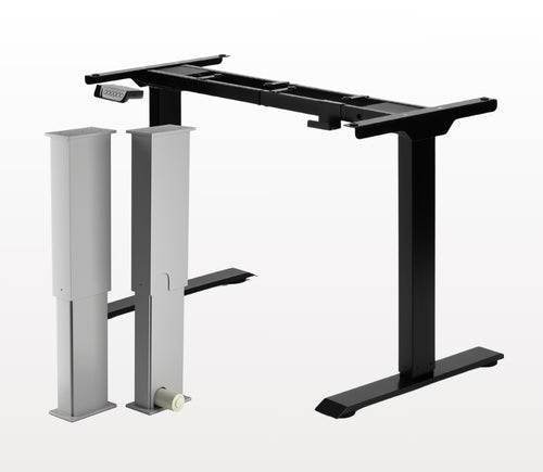
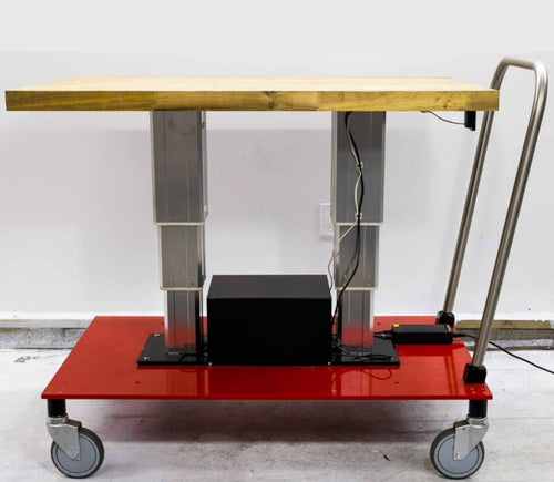
Áno, stojaci stôl v tvare L je prispôsobivý orientácii a môžete ho nainštalovať podľa svojich preferencií. Tu je podrobný návod krok za krokom, ktorý vysvetľuje, ako je to možné: FLT-05 Používateľská príručka
POZNÁMKA: Nasledujúce kroky sa môžu líšiť v závislosti od modelu vášho diaľkového ovládača. Tieto pokyny sú pripravené pre štandardný diaľkový ovládač RT-11. Ak chcete nastaviť maximálnu výšku rámu, prejdite na požadovanú výšku a postupujte podľa týchto krokov:
- Stlačte M; na displeji sa zobrazí [5 -]
- Stlačte tlačidlo UP; [5 -] bliká
- Podržte tlačidlo M, kým sa na displeji nezobrazí [999]
- Maximálna výška je teraz nastavená
Ak chcete nastaviť minimálnu výšku rámu, prejdite na požadovanú výšku a postupujte podľa týchto krokov:
- Stlačte M; na displeji sa zobrazí [5 -]
- Stlačte tlačidlo DOWN; [5 -] bliká
- Podržte tlačidlo M, kým sa na displeji nezobrazí [000]
- Minimálna výška je teraz nastavená
Ak chcete limity resetovať, postupujte podľa nasledujúcich krokov:
- Stlačte M, kým sa na displeji zobrazí [5 -], potom uvoľnite
- Podržte M, kým neuvidíte [555]
- Limity boli resetované
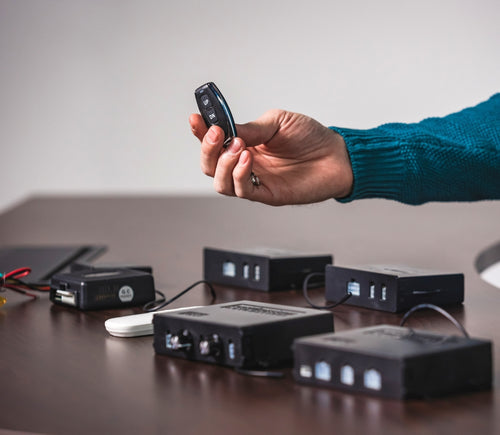
POZNÁMKA: Kroky nižšie sa môžu líšiť v závislosti od modelu vášho diaľkového ovládača. Nasledujúce pokyny sú určené pre štandardný diaľkový ovládač RT-11.
Ak musíte držať tlačidlá diaľkového ovládania, aby ste dosiahli svoju predvolenú výšku, znamená to, že vaša riadiaca jednotka je v momentary režime. Ak chcete prepnúť diaľkové ovládanie do non‑momentary režimu, postupujte podľa týchto krokov
- Uistite sa, že pod stolom nič nie je, pretože musíme spustiť resetovací postup
- Stlačte a podržte tlačidlo DOWN, kým sa na displeji nezobrazí [ASr]
- Keď sa zobrazí [ASr], stlačte a podržte [1]; môžete vidieť dve hodnoty:
a. 10.1 = Non‑momentary režim
b. 10.2 = Momentary režim
- Dokončite resetovací postup podržaním tlačidla DOWN, kým sa váš stôl mierne nespustí a znovu nezodvihne.
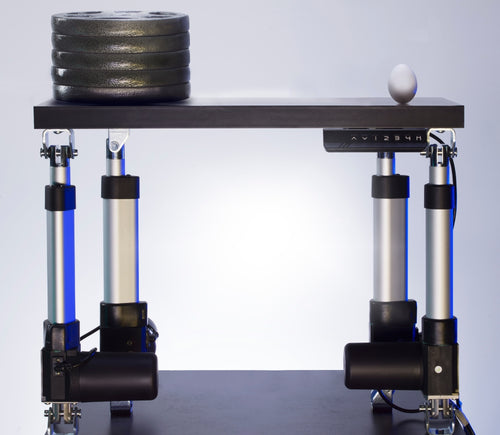
Naše stojace stoly majú 3 nastavenia detekcie kolízie a tieto nastavenia si môžete prispôsobiť podľa svojich preferencií. Postupujte podľa nasledujúcich krokov:
- Uistite sa, že pod stolom nič nie je, keďže musíme spustiť resetovací postup
- Stlačte a podržte tlačidlo DOWN, kým sa na displeji nezobrazí [ASr]
- Keď sa zobrazí [ASr], stlačte a podržte tlačidlo UP [ ^ ]; môžete vidieť tri hodnoty:
a. 10.5 = 11 lbs
b. 10.6 = 22 lbs
c. 10.7 = 33 lbs
- Dokončite resetovací postup podržaním tlačidla DOWN, kým sa váš stôl mierne nespustí a znovu nezodvihne.
Máme pre vás niekoľko krokov na riešenie problémov, ak sa na rámoch s riadiacimi jednotkami série FLTCON zobrazí niektorý z nasledujúcich chybových kódov:
Skontrolujte chybový kód tu.
Ak problém pretrváva aj po vykonaní týchto krokov, obráťte sa na našich technických produktových inžinierov na čísle 1-800-676-6123 alebo nám napíšte na sales@progressiveautomations.com.